 |
|||
|
|
|||
|
|
|||
| ||||||||||
|
| 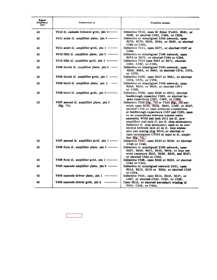 unit 4 to 550 mc (the center of the low-band
c. Rf Chart. When the tests in b above
frequency range), and proceed as indicated
show that the trouble is not in the if. am-
in the chart below. After the tests of the
p l i f i e r , the if. step attenuator, nor in the
l o w - b a n d rf tuner have been checked out
i f . preamplifier, proceed with the tests
s a t i s f a c t o r i l y , rotate the band switch to
listed in the chart below. Use tuning unit
700-1,000 mc; then set tuning unit 4
4 signal generator (para 65) with 1,000-ops
s i g n a l generator and the TUNING dial of
modulation. Since tuning unit 4 uses band
s w i t c h i n g , first rotate the band switch to
tuning unit 4 to 850 mc (the center of the
h i g h - b a n d frequency range) and perform
400-700 mc; then set tuning unit 4 signal
t h e tests indicated.
generator and the TUNING dial of tuning
163
|
|
Privacy Statement - Press Release - Copyright Information. - Contact Us |
