 |
|||
|
|
|||
|
|
|||
| ||||||||||
|
| 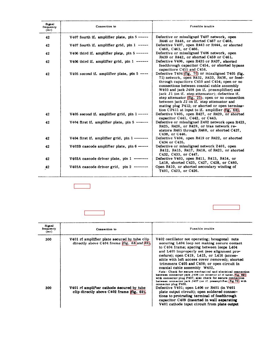 m o d u l a t i o n . Since tuning unit 3 does not
use band switching, set tuning unit 3 signal
b above show that the trouble is not in the
generator and the TUNING dial of tuning
i f . amplifier, the if. step attenuator, and
u n i t 3 to 300 mc (the center of the fre-
the if. preamplifier, proceed with the tests
q u e n c y range). R e f e r t o f i g u r e 6 9 a n d
listed in the chart below. Use tuning unit
proceed as follows:
3 signal generator (para 65) with 400-cps
161
|
|
Privacy Statement - Press Release - Copyright Information. - Contact Us |
