 |
|||
|
|
|||
|
|
|||
| ||||||||||
|
|  Mast Sections AB-21/GR. The vertical
v o l t a g e causes a current to flow
a n t e n n a base is similar to Antenna AT-
t h r o u g h the same circuit path as
1 0 2 6 / U R M - 8 5 (a above). It houses the
that of the unknown signal. In this
m a t c h i n g transformers, and injection net-
manner, a direct comparison of the
work for the impulse generator signal, and
amplitude of the rf incoming signal,
a band switch to select one of the six bands
with reference to the impulse gen-
c o r r e s p o n d i n g in frequency to that in-
e r a t o r signal, is obtained without
scribed on the front panel of tuning unit 1.
transformation
introducing
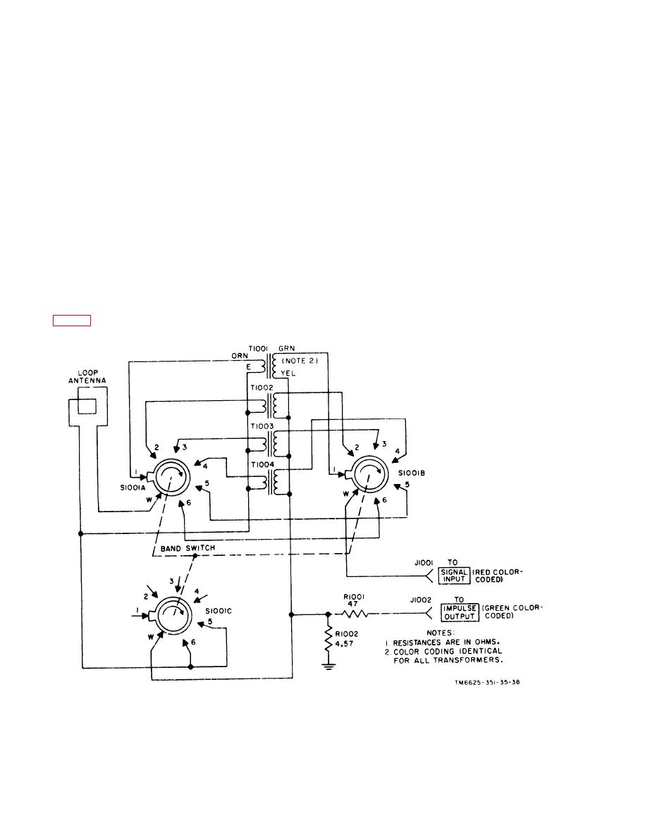
(1) Rf signal path. With the five
factors.
l e n g t h s of Mast Sections AB-21/
(3) A t t e n u a t o r p a d . A 2 0 - d b a t t e n -
GR connected to the socket at the
uator pad. which consists of R1001
top of the vertical antenna base, the
and R1002, is always in the path of
impedance of the antenna is high,
t h e impulse generator signal when
b u t varies with the frequency of
the loop antenna is used. This at-
t h e incoming rf signal. To match
tenuation is counterbalanced by the
the output of the antenna to the red
f a c t that the level of the impulse
color-coded 50-ohm impedance
g e n e r a t o r signal is actually 20-db
m a t i n g r f coaxial cable, six
h i g h e r than that indicated by the
m a t c h i n g stepdown transformers,
s e t t i n g s of the main unit impulse
T 1 1 0 1 through T1106, are used.
output coarse and fine controls.
T h e construction of these trans-
b. Coupler, Antenna CU-890/URM-85
f o r m e r s is identical with that for
t h o s e used in the loop antenna (a
to support five series--connected lenghts of
Figure
36.
Antenna
AT-1026/URM-86,
schematic
diagram.
82
|
|
Privacy Statement - Press Release - Copyright Information. - Contact Us |
