 |
|||
|
|
|||
|
Page Title:
Section VII. THEORY OF MINOR COMPONENTS |
|
||
| ||||||||||
|
| 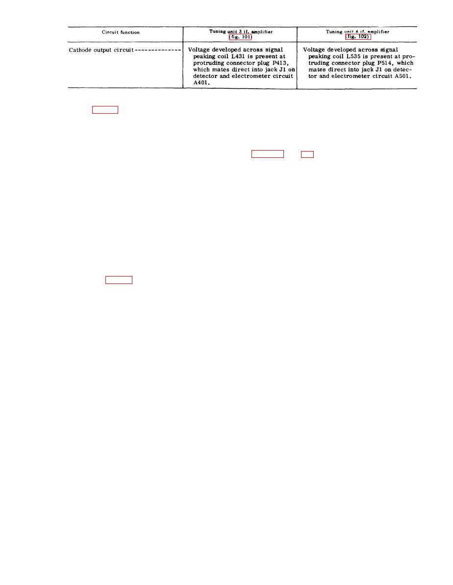 58. Detector and Electrometer Circuit A501
channels, and applies output signals to the
appropriate circuits in the main unit.
T h e s e sealed circuits are interchangeable
A l l tuning units employ an identical
with each other and perform the functions
s e a l e d detector and electrometer circuit.
d e s c r i b e d in detail for detector and elec-
E a c h circuit accepts driving power from
t r o m e t e r circuit A1 within tuning unit 1
the if. amplifier, detects the signal in sep-
arate a u d i o a n d d c m e t e r i n g s i g n a l
Section VII. THEORY OF MINOR COMPONENTS
rite cup cores to obtain proper
59. Minor Components for Use with
s h i e l d i n g f r o m stray magnetic
Tuning Unit 1
fields. The proper step-up ratio is
Five minor components are supplied for
o b t a i n e d by rotating band switch
use with tuning unit 1. A physical descrip-
S1001, at the front of the housing,
tion of these components is given in TM
to the same frequency band in use
11-6625-351-12.
The following circuit
by tuning unit 1. For band 5 (5.2-
a n a l y s i s supplement the information con-
t o 12.7-mc) and band 6 (12.7- to
tained in TM 11-6625-351-12.
30-mc), the loop impedance is
c l o s e to 50-ohms and no step-up
t r a n s f o r m e r is required.
of wire and a base which houses matching
(2) Impulse generator signal p a t h.
transformers, an injection network for the
When the loop antenna over the fre-
impulse generator signal, and a band
q u e n c y range of tuning unit 1 is
switch to select one of the six bands cor-
used, calibration of the test set is
r e s p o n d i n g in frequency to that inscribed
accomplished by injecting a voltage
o n the front panel of tuning unit 1. The
from the impulse generator in
loop itself consists of a single turn of wire
s e r i e s with the secondary winding
enclosed in an electrostatic shield. There-
of the selected matching trans-
f o r e , the loop is relatively insensitive to
former. For bands 5 and 6, section
the electric field component of radio
C of switch S1001 conducts the im-
e n e r g y but is highly responsive to the
pulse generator signal in series
magnetic field component. Because of the
with the loop itself. Sections A and
single turn of wire in the loop itself, this
B of the switch then provide a dc
a n t e n n a has an extremely low-output im-
path to output connector J1001. The
p e d a n c e match.
i m p u l s e generator signal path is
from the main unit IMPULSE OUT-
(1) Rf signal path. To match the out-
P U T front-panel jack, through the
put impedance of the loop antenna
g r e e n color-coded mating rf cable
to the red color-coded 50-ohm
to the injection network built into
characteristic impedance of the
t h e green color-coded signal con-
mating c o a x i a l r f c a b l e , f o u r
nector J1002. When the calibrating
matching transformers,
T1001
voltage from the impulse generator
through T1004, are used. The
of subminiature
circuit is injected in series with the
incoming rf signal, the calibrating
c o n s t r u c t i o n , are enclosed in fer-
81
|
|
Privacy Statement - Press Release - Copyright Information. - Contact Us |
