 |
|||
|
|
|||
|
Page Title:
Figure 22. Tuning unit 2, mixer and oscillator (20-70 mc), schematic diagram. |
|
||
| ||||||||||
|
| 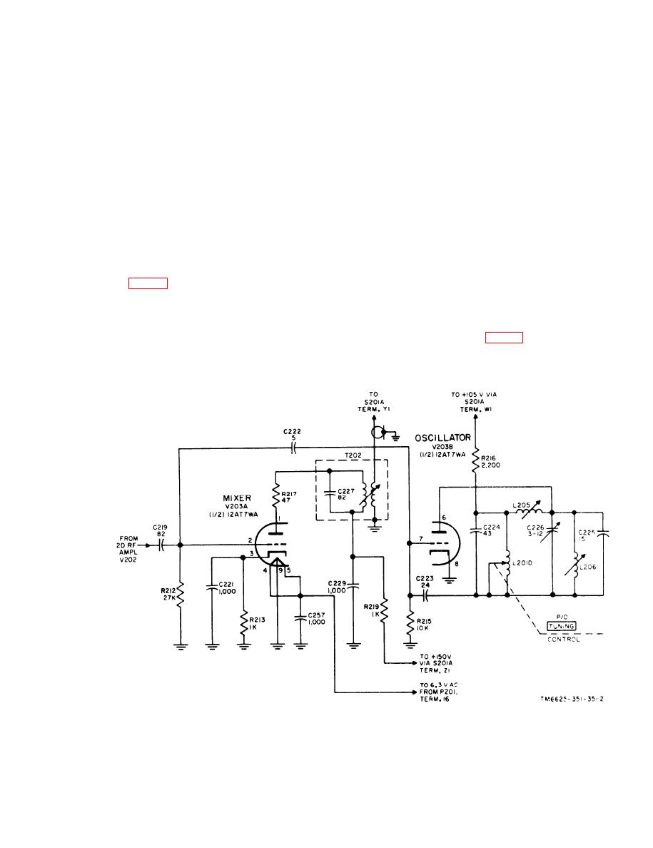 circuit of which is tuned to the difference
R e s i s t o r R 2 0 7 , the screen-dropping re-
f r e q u e n c y of 10.7 mc.
s i s t e r , is bypassed by C241. The rf output
v o l t a g e in the plate circuit is developed
a. Mixer V203A. The s i g n a l voltage
across the tuned plate circuit, which con-
f r o m second rf amplifier V202 is applied
s i s t s of tuning inductor L201C, capacitor
through coupling capacitor C219 to the grid
C 2 1 7 , coil L204, and trimmer capacitor
(pin 2) of the mixer. The voltage generated
C 2 1 8 . Resistors R208 and R211 are used
by oscillator V203B is also applied to the
t o load the plate tuned circuits. Resistor
g r i d of the mixer by coupling capacitor
R 2 1 4 and capacitor C216 provide plate
C 2 2 2 . The input voltages are developed
circuit decoupling. Bypass capacitor C259
a c r o s s grid resistor R212. Cathode bias
p r e v e n t s rf currents from circulating in
i s developed by the current flow through
t h e heater circuit. The voltage across the
R 2 1 3 , which is bypassed by C221. Re-
p l a t e tuned circuit is coupled to the grid
s i s t o r R219 and capacitor C229 provide
o f mixer stage V203A through capacitor
decoupling for the plate circuit. The plate
C219.
c i r c u i t load consists of the primary of rf
t r a n s f o r m e r T202 and its parallel capac-
36. Rf Tuner, Analysis of 20-70-Mc Mixer
i t o r C227. Resistor R217 functions as a
and Oscillator
p a r a s i t i c oscillation suppressor. Bypass
c a p a c i t o r C257 prevents Tf currents from
c i r c u l a t i n g in the 6.3-volt ac heater cir-
T h e mixer stage, V203A, receives sig-
cuit. The 10.7-mc output of the mixer
n a l s from second rf amplifier V202 and
voltage is fed through switch S201A to if.
from oscillator V203B. The oscillator
step attenuator A201 (fig. 25).
g e n e r a t e s a frequency which is 10.7 mc
b. Oscillator V203B. A p l a t e tuned
higher than the signal frequency. The two
o s c i l l a t o r is used to generate the local
signals are mixed within V203A, the plate
Figure 22. Tuning unit 2, mixer and oscillator (20-70 mc), schematic diagram.
51
|
|
Privacy Statement - Press Release - Copyright Information. - Contact Us |
