 |
|||
|
|
|||
|
Page Title:
Figure 10. Cathode follower and meter circuit, ZERO ADJ position of function switch. |
|
||
| ||||||||||
|
| 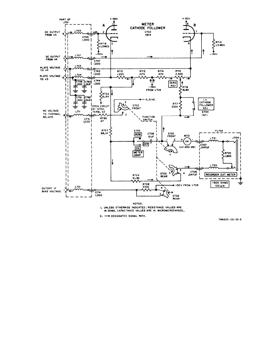 F i g u r e 10. Cathode follower and meter circuit, ZERO ADJ position of function switch.
w a f e r has been rotated 90 clockwise from
function switch, because only the equaliz-
i t s original CW AVERAGE position. The
i n g voltage across the metering circuit
long tab on the switch wafer continues to
w a s of interest. With the function switch
create a path of continuity for the output
i n PULSE PEAK position, however, it is
o f cathode follower between terminals 3
i m p o r t a n t to note the value of resistance
and 4. The signal path for V702A cathode
i n the meter multiplier path. The com-
i s through multiplier resistors R723 and
b i n e d value of multiplier resistors R723
R724, instead of through single multiplier
and R724 is approximately twice the value
R722. This increase in resistance value of
o f multiplier resistor R722. Therefore,
the multiplier circuit was of little signif-
the meter is approximately 6 db less
i c a n c e in the ZERO ADJ position of the
sensitive in PULSE PEAK position than in
27
|
|
Privacy Statement - Press Release - Copyright Information. - Contact Us |
