 |
|||
|
|
|||
|
Page Title:
Description of Transponder Set AN/APX-44 |
|
||
| ||||||||||
|
|  equipment configuration technical manual.
Set AN/APX-44
Radar RT-494/APX-44
a. The transponder set consists of Re-
c e i v e r - T r a n s m i t t e r , Radar RT-494/APX-
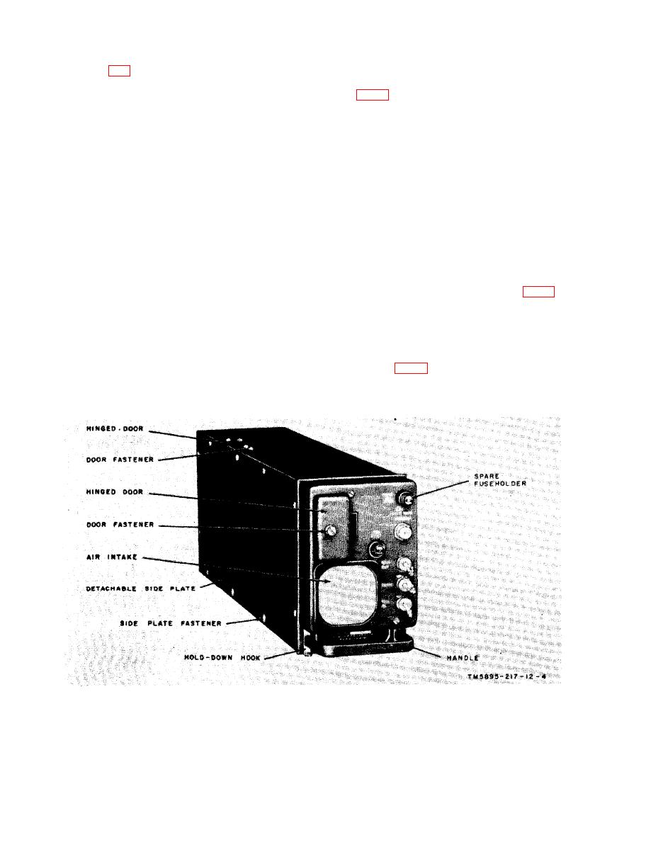
a. The receiver-transmitter is a sep-
4 4 , Mounting MT-2100/APX-44, Control,
arately housed unit containing the receiver
Transponder Set C-2714/APX-44, and
a n d transmitter circuits of the trans-
Antenna AT-884/APX-44. The intercon-
ponder set. A handle is attached to the unit
necting cables, through which all the com-
for convenient handling. On the top of the
ponents are interconnected, are supplied
case is a hinged door through which the
as part of the aircraft in which the
plug-in delay line (not shown) is installed
transponder set is installed.
or removed. On the front of the receiver-
b. The receiver-transmitter is secured
transmitter is a hinged door which is held
t o the mounting which is bolted to a
secure with a door fastener. The front
mounting surface within the aircraft. When
p a n e l also has an air intake, two fuse-
a multipin connector (not shown) is at-
holders, and four coaxial connector jacks.
tached to the cutout on the mounting, con-
b. Two holddown hooks, located at the
nections are made to the aircraft battery
bottom lip of the front panel mate with the
and the control unit. The antenna is con-
holddown clamps on the mounting (fig. 5).
nected to a coaxial cable connector on the
Holes are provided on the rear panel that
f r o n t panel of the receiver-transmitter.
mate with the index pins of the mounting.
The control unit is mounted on the air-
Detachable side plates, attached with quick
craft instrument panel, and the antenna is
disconnect side mate fasteners, are loca-
m o u n t e d on the outside of the aircraft.
t e d on each side of the receiver-trans-
For location of equipment within an air-
mitter case (fig. 2).
c r a f t , refer to the aircraft's electronics
Receiver-Transmitter,
Radar
RT-494/Apx-44.
|
|
Privacy Statement - Press Release - Copyright Information. - Contact Us |
