 |
|||
|
|
|||
|
Page Title:
Table 4-11. MODULE TEST SET CONTROLS AND INDICATORS (Cont'd) |
|
||
| ||||||||||
|
|  TM 11-5895-1141-34
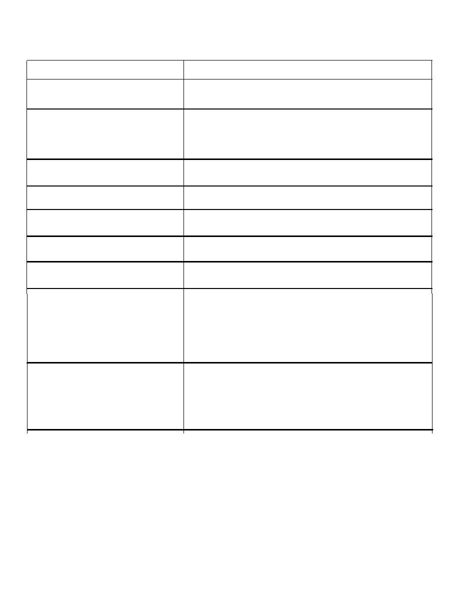
Table 4-11. MODULE TEST SET CONTROLS AND INDICATORS (Cont'd)
Controls/indicators or
Function
Connector
INTERLOCK/OFF switch S8
Simulates keying of the channel at
another operator's position.
CHANNEL BUSY indicator DS4
Lights to indicate simulated channel
engagement - when INTERLOCK switch S8
is set to INTERLOCK or when selector
module switch is ON and S7 is set to
P/T KEY.
MUTE OTHERS/OFF switch S14
Not used in these tests - leave at
OFF .
MUTE BUS ACTIVE indicator
Not used in these tests.
DS5
CONTR/INST switch S15
Not used in these tests - leave at
INSTR.
CHAN KEYED/CONTR headset
Not used in these tests - leave at
switch S16
OFF.
CHAN KEYED/TELCO switch S17
Not used in these tests - leave at
OFF.
CONTR Headset Connector J7
The test signal appearing at this con-
and J11
nector is cabled to the controller
headset microphone input on the jack
unit. When this jack is not plugged
in the internal test set, signals will
be routed directly to the microphone
amplifier lamp brightener module
input.
INSTR headset connector J8
The test signal appearing at this con-
and J9
nector is cabled to the instructor
headset input on the jack unit. When
this jack is not plugged in the inter-
nal test set, signals will be routed
directly to the microphone amplifier
lamp brightener module input.
4-28
|
|
Privacy Statement - Press Release - Copyright Information. - Contact Us |
