 |
|||
|
|
|||
|
Page Title:
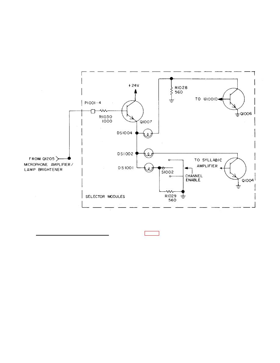
Figure 2-7. Indicator Lamp Circuits |
|
||
| ||||||||||
|
|  TM 11-5895-1141-34
approximately 12 to 22 volts, suitable for ambient light conditions ranging from darkness to daylight. The green lamp DS1
is illuminated whenever switch S2 is moved to the LOCK or NONLOCK positions; the amber and red lamps, DS2 and DS4,
are illuminated by the conduction of transistors Q4 and Q6 respectively. In the absence of conduction through the switch
or transistor Q6, resistors R29 and R28 allow backlighting current to flow through lamps DS1 and DS4. This current
causes the lamps to glow dimly with respect to their intensity when actuated, but the dim glow is sufficient to facilitate
location and identification of the selector module in darkness.
Figure 2-7. Indicator Lamp Circuits
(2) Audio Signal Circuits (Transmitting). Refer to figure FO-17. The regulated microphone signal distributed from
the audio unit assembly to P1-21 is coupled to emitter follower stage Q10, which in turn drives Q11, whose output
resistance is a nominal 600 ohms, due to resistor R37. This signal is supplied via transformer T2 to P1 pins 10, 11 via a
form C contact set of the relay K1. When the operator is transmitting, K1 is energized, completing the circuit through
normally-open contact. Otherwise, the transmitter audio line is terminated by resistor R51 through the normally-closed
contact. It is wired to a pair of terminals rather than the printed wiring of the circuit board.
2-19
|
|
Privacy Statement - Press Release - Copyright Information. - Contact Us |
