 |
|||
|
|
|||
|
Page Title:
REMOVAL AND REPLACEMENT OF PARTS ON THUMBWHEEL SWITCH ASSEMBLIES. |
|
||
| ||||||||||
|
|  T.O. 12P4-2APX-142
NAVAIR 16-35C6280-1
TM 11-5841-268-25
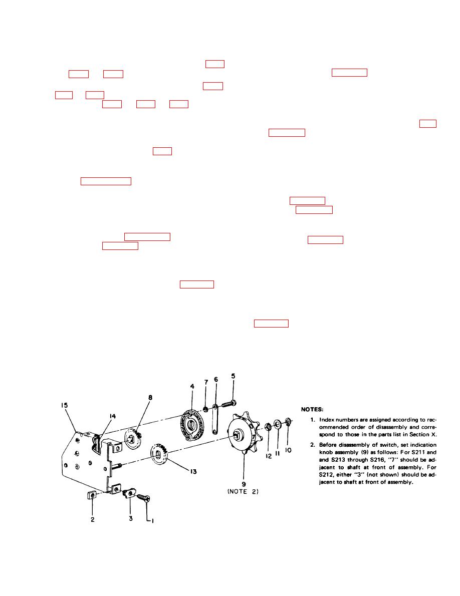
remove wafer from shaft. Check that flats on sides of shaft
that holds switch assembly to angle bracket (49, FO3; p/o
are vertical, as shown in Figure 81, and reinstall shaft in
hole in chassis (15), making sure the gear teeth mesh with
the teeth of the gear on the chassis assembly.
Step 3. Apply a small amount of Lubricant 551D7-44 to
gear teeth, as necessary. Remove any excess lubricant.
Step 4. Remove thumbwheel switch assembly.
Step 5. To install thumbwheel switch assembly, reverse
and Figure 81 (flat side vertical, notch toward front of
the procedures in Steps 2 and 3.
switch assembly), and install wafer on shaft of shaft and
gear assembly.
thumbwheel switch assembly.
Step 5. Replace washers (7), spring tension clip (6), and
screws (5).
Step 7. Replace the plastic light panel and rear panel as-
sembly (paragraphs 83 and 85).
822. REPLACEMENT OF INDICATION KNOB ASSEM-
BLY. Except for S212, to replace the indication knob as-
8-19. REMOVAL AND REPLACEMENT OF PARTS ON
sembly (9, Figure 81), check that the knob is set to "7,"
THUMBWHEEL SWITCH ASSEMBLIES.
as shown in Figure 81. For S212, set the knob to "3."
820. GENERAL. To remove and replace parts on the
Then, proceed as follows:
thumbwheel switch assemblies, remove switch assembly from
Step 1. Using C-ring expanding tool, carefully spread re-
transponder set control (paragraph 817). Refer to the ex-
taining ring (10, Figure 81). Remove ring, flat washer or
ploded view in Figure 81 and to the appropriate procedure
washers (11), and spring washer (12).
in paragraph 8--21 or 8--22 for parts replacement. When the
Step 2. Lift indication knob (9) and spur gear (13), which
repair is completed, reinstall the switch assembly.
is attached to knob, from shaft.
821. REPLACEMENT OF SWITCH WAFER. To replace
Step 3. Install spur gear on replacement indication knob.
the switch wafer of the rotary switch (4, Figure 81 ), check
Step 4. Apply a small amount of Lubricant 551D744 to
that indication knob assembly (9) of all switches, except
gear teeth, as necessary. Remove any excess lubricant.
S212, is set to "7." Set S212 to "3." Then, proceed as
follows:
Step 5. Orient spur gear and indication knob as shown in
Step 1. Remove two screws (5), spring tension clip (6),
gear on shaft.
and two washers (7) that fasten switch to chassis ( 15).
Step 6. Replace spring washer (12), flat washers (11) as
Step 2. Lift switch wafer from shaft of shaft and gear
required, and retaining ring (10).
assembly (8). If shaft and gear assembly lift up with wafer,
Figure 81. Thumbwheel Switch Assembly, Exploded View
83
|
|
Privacy Statement - Press Release - Copyright Information. - Contact Us |
