 |
|||
|
|
|||
|
Page Title:
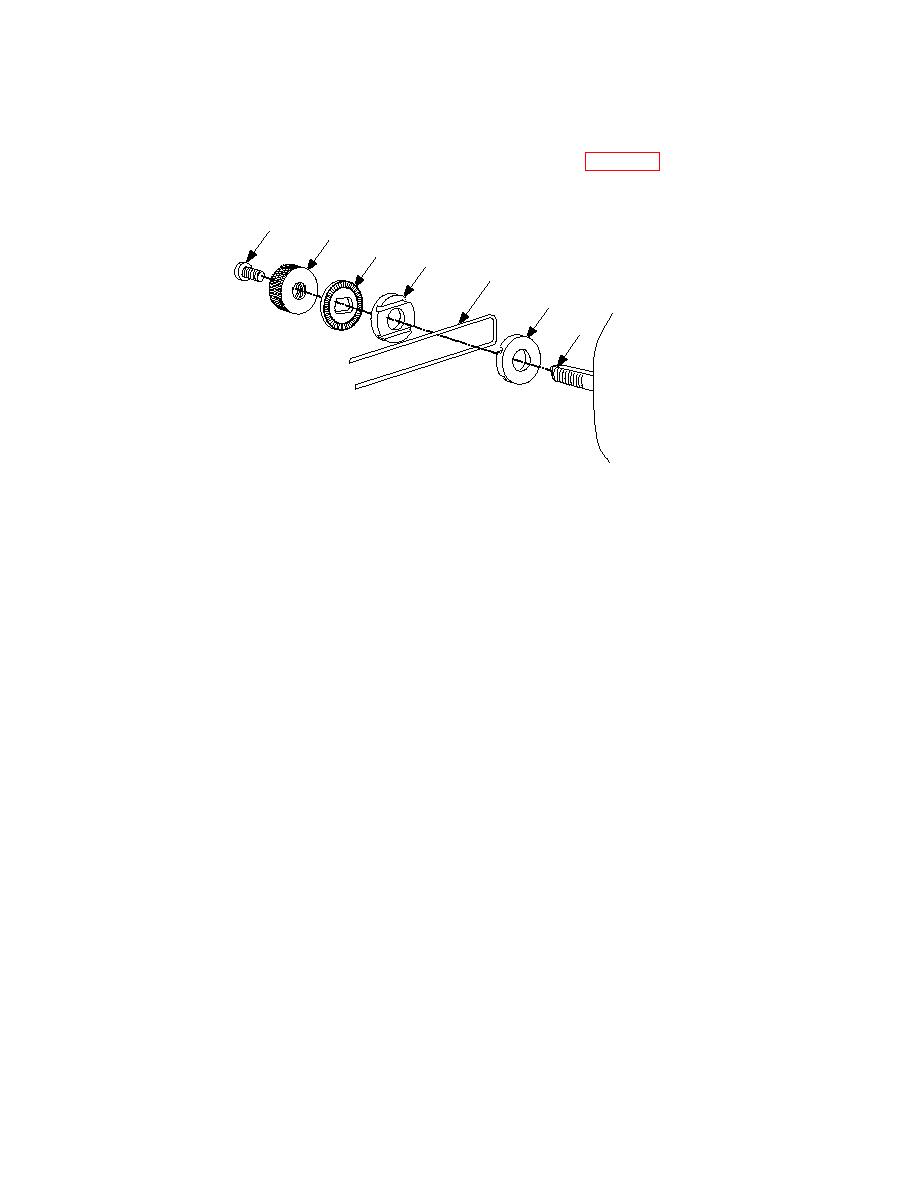
Boom Assembly/Mounting Hardware Removal and Replacement (Fig. 3-14) |
|
||
| ||||||||||
|
|  TM 11-5830-263-20&P
3.8.4.
Boom Assembly/Mounting Hardware Removal and Replacement (Fig. 3-14)
1
2
3
4
5
4
6
a. Removal
1. Using a cross-tipped screwdriver remove screw (1) securing mounting hardware to headset.
2. Unscrew knurled thumbnut (2).
3. Remove boom clamp (3), boom guides (4), and boom assembly (5) by sliding off mounting
post (6)
b. Replacement
1. Align boom assembly (5) arms into slots between the two boom guides (4) and hold in place.
2. Place, boom guides (4) with boom assembly (5) on the mounting post (6) and hold in place.
3. Place boom clamp (3) on mounting post (6) so that the serrated edge is flush against the
boom guide (4) and hold in place.
4. Place knurled thumb nut (2) on mounting post (6) and turn clockwise and tighten until secure.
5. Using a cross tipped screwdriver place screw (1) in end of mounting post (6) and tighten until
secured.
|
|
Privacy Statement - Press Release - Copyright Information. - Contact Us |
