 |
|||
|
|
|||
|
Page Title:
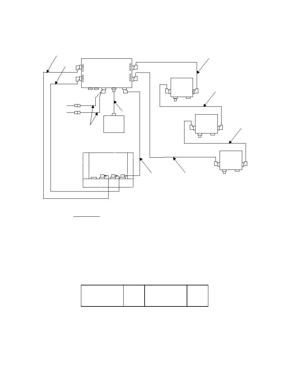
Figure 2-32. MLRS System Configuration Diagram |
|
||
| ||||||||||
|
|  TM-11-5830-263-20&P
1
4
MCS
P1
1
A3205747
P1
CHIEF
P1
P2
FFCS 1
EXTERNAL
LOUD
A3205746
LINE
ALARM SPEAKER
POWER
5
P1
P1
P2
P3
(4W2P3)
P1
GUNNER
3
P2
(W327P1)
FFCS 2
LOUD-
or (W4P3)*
A3205746
SPEAKER
4
A3206080
2
P1
P2
DRIVER
(RADIO, SINCGARS)
FFCS 3
RT-A / RT-B
A3205746
P1
P2
P2
P2
P2
4
6
A4J1 A4J3 A4J4 A4J2
* P2 connector of Alarm cable attached to W327P2 in M270A1 vehicles. P2 connector of Alarm cable attached to W4P3 in M270
vehicles.
EXISTING COMPONENTS
CABLE PART NUMBERS FOR
MLRS
1.
A3206019-3
(RECEIVE/TRANSMIT)
2.
A3206618
(CABLE, SPEC PRP)
3.
A3206193-30
(LOUDSPEAKER)
4.
A3206018-4
(HIGHWAY)
5.
A3206018-6
(HIGHWAY)
6.
A3206017-3
(POWER)
RING SEQUENCE FOR MLRS
FROM VIS BOX
CABLE
TO VIS BOX
CABLE
MCS (TOP CONN)
#4 (P1)
FFCS 1
#4 (P2)
FFCS 1
#5 (P1)
FFCS 2
#5 (P2)
FFCS 2
#4 (P1)
FFCS 3
#4 (P2)
FFCS 3
#4 (P1)
MCS (BOT CONN)
#4 (P2)
|
|
Privacy Statement - Press Release - Copyright Information. - Contact Us |
