 |
|||
|
|
|||
|
Page Title:
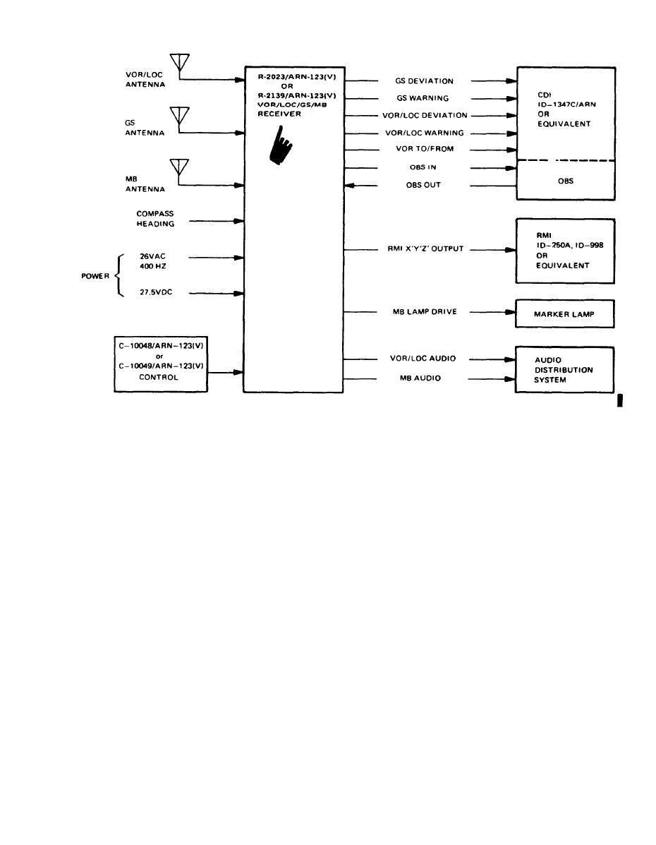
Figure 1-3. System Application. |
|
||
| ||||||||||
|
|  TM 11-5826-258-24
EL00N001
Figure 1-3. System Application.
Table 1-1. Tabulated Data-Continued
Accuracy
Manual VOR
Bearing error leas than 0.75 under the conditions of paragraph 2.1.1 of
DO- 153 using a precision tracking selector.
Automatic VOR
Bearing error leas than 2.0 under the conditions of paragraph 2.4 of DO- 153.
Centering error lees than 6.3 millivolt-s (Class D) under the conditions of para-
Localizer
graph 2.1 of RTCA Document DO-131.
Deflection sensitivity:
150 10 millivolts for 10 course offset.
VOR
90 millivolts for a 0.093 DDM with a deflection linearity of 90 9 millivolts at
Localizer
0.093 DDM.
Adjustable balanced output which provides 50 milliwatts into 150-ohm external
Audio output power
load.
Audio output will not vary more than 6 db from 350 Hz to 2500 Hz.
Audio frequency response
Less than 25% with a 50 to 20,000 v standard audio test signal
Harmonic distortion
More than 50 db.
Manual gain control
sensitivity:
Audio (VOR and localizer)
Does not require more than 3.0 microvolt rf input signal modulated 30% by 1000
Hz for a 6-db signal-plus-noise-to-noise ratio.
RF, VOR
Does not require more than 3.0 microvolt standard VOR teat signal for fully con-
cealed VOR flag and satisfactory navigation performance.
RF, localizer
Does not require more than 3.0 microvolt standard localizer test signal for fully
concealed localizer flag and satisfactory navigation performance.
VOR adjacent channel
Bearing information will not change more than 10 because of adjacent channel
signals.
Automatic indication will be within 3 of new bearing, within 15 seconds after an
Time response
offset course of 180 is abruptly applied.
Damping characteristics:
VOR
When the difference in phase between the two components of an on course stand-
ard VOR teat signal of 1000 microvolt is abruptly changed, the pointer of a
CDI ID-1347 C/ARN equivalent will reach 70% of its ultimate position within
3.5 seconds for the R-2023/ARN-123(V) or 5.7 seconds for the R-2139/
ARN-123(V) and the pointer overshoot will not exceed 20%.
Change 1
1-5
|
|
Privacy Statement - Press Release - Copyright Information. - Contact Us |
