 |
|||
|
|
|||
|
Page Title:
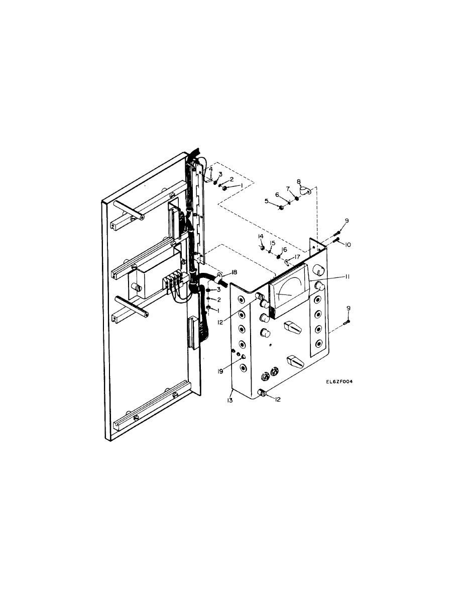
Figure 3-1. Removal and Replacement of Control Panel Assembly |
|
||
| ||||||||||
|
|  TM 11-5825-271-34
(2) Aline three holes in control panel assembly
control panel assembly (13) by installing cable clamp (8)
(13) with three holes in the hinge on board chassis, and
removed in 3-6b(1), above.
insert three screws (9) from outside of control panel
(6) Remove two nuts (14), lockwashers (15),
assembly (13).
and flat Washers (16) from the back of TEST meter M1
(3) Place solder lug (4) and cable clamp (18) on
(11) and reinstall two solder lugs (17).
two of the three screws (9) as noted in 3-6a(5), above.
(7) Solder all tagged wires from the cableform to
(4) Secure control panel assembly (13) using
the control panel components, and slide rubber sleevings
three flat washers (3), lockwashers (2), and nuts (1).
over the connections.
(5) Secure portion of cableform near R1 on the
(8) Swing the control panel assembly (13) in
and tighten two captive screws (12).
I. NUT
II.
TEST METER
2. LOCKWASHER
12.
CAPTIVE SCREW
3. FLATWASHER
13.
CONTROL PANEL ASSEMBLY
4. SOLDER LUG
14.
NUT
5. NUT
15.
LOCKWASHER
6. LOCKWASHER
16.
FLATWASHER
7. FLATWASHER
17.
SOLDER LUG
8. CABLE CLAMP
18.
CABLE CLAMP
9. SCREW
19.
SWITCH SI
10. SCREW
Figure 3-1. Removal and Replacement of Control Panel Assembly
3-2
|
|
Privacy Statement - Press Release - Copyright Information. - Contact Us |
