 |
|||
|
|
|||
|
|
|||
| ||||||||||
|
|  TM 11-5825-270-23
level troubleshooting has been performed (i.e., fuses
operational condition.
and lamps have been checked and were either good or
4-7. Maintenance Turn On Procedure
continuously blowing).
WARNING
a. A maintenance turn on procedure is provided
Always turn the power off and
remove the ac power cord from J2 at
malfunctions.
These procedures reference the
the back of the receiver before
applicable malfunction in troubleshooting table 4-3.
performing any of the replacement
Each step of the maintenance turn on procedure
procedures.
assumes that all previous tests were performed
satisfactorily.
NOTE
b. Troubleshooting procedures should be preceded
After a fault has been located and
by a thorough visual inspection and a check for burnt or
cleared, carry out all tests that are
discolored resistors, broken or disconnected wiring or
referenced
in
the
replacement
other abnormalities that may indicate the circuit at fault.
procedures.
power to the monitor receiver is correct and that operator
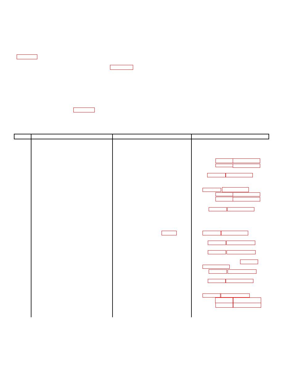
Table 4-2. Maintenance Turn On-Procedure
Step
Procedure
Observation
Corrective Action
1
Examine all connections at rear of
All connections will be secure.
Tighten as required.
receiver.
2
Verify that the NDB transmitter
None.
None.
is operating satisfactorily.
3
Set POWER switch to ON, then
a. Indicating fuse will be off.
momentarily press the ALARM SIL
b. POWER indicator will be on.
switch.
c. NORM indicator will be on and
c. If both indicators are off refer
ALARM indicator will be off.
to table 4-3, malfunction 4. If
NORM indicator is off and
ALARM indicator is on, refer to
d. Remote alarm will be off.
e. CARRIER LEVEL meter will
read 01 dB.
4
Set AUDIO LEVEL control to
Keying will be heard in the loud-
Refer to table 4-3, malfunction 8.
approximately midposition.
speaker.
5
Turn front panel latch and swing
None.
None.
the front panel door open.
6
During the keying sequence press
After the delay set by TIME DE-
a. If the delay is wrong refer to
the ALARM TEST switch and hold
LAY control A2R32 (fig. 2-1) the
it pressed.
NORM indicator will be on, the
b. If the receiver does not alarm refer
aural alarm will sound, and the
remote alarm will be on.
c. If there is no aural alarm refer
d. If the NORM and ALARM indicators
are both off refer to table 4-3,
7
Press the ALARM SIL switch.
The aural alarm will be off.
Refer to table 4-3, malfunction 12.
8
Release the ALARM TEST switch.
a. Norm indicator will be .on and
a. If both indicators are off refer
ALARM indicator will be off.
to table 4-3, malfunction 4. if
NORM indicator is OFF and
ALARM indicator is on refer to
b. Remote alarm will be off.
c. CARRIER LEVEL meter will
read 0 dB.
4-2
|
|
Privacy Statement - Press Release - Copyright Information. - Contact Us |
|
|
Integrated Publishing, Inc. - A (SDVOSB) Service Disabled Veteran Owned Small Business
|

