|
| |
TM 11-5821-333-12
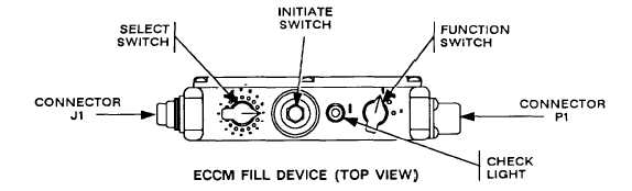
2-11. ECCM FILL DEVICE CONTROLS, INDICATORS, AND CONNECTORS.
P1 CONNECTOR. This connector will mate with a connector such as J1 and provides the capability to load ECCM
data from another fill device.
FUNCTION SWITCH. This switch is used to turn the fill device on and off as well as to erase data in the fill device
when the switch is placed in the spring loaded ZA (zero all) position. To erase, the initiate switch must be
pressed.
CHECK LIGHT. Blinks when data is transferred to RT. Also blinks when select switch position contains data,
function switch is set to OFF, and initiate switch is pressed.
INITIATE SWITCH. This switch is used for the following:
To ask for data during fill device loading,
To check if a select switch position has data in it,
To erase data in the fill device.
SELECT SWITCH. This switch selects which FH data or TRANSEC variable will be stored or transferred. The A
position is used to transfer all data from one fill device to another. Positions 1-13 are for FH data sets. Positions
T1 and T2 are for TRANSEC variables.
J1 CONNECTOR. Connects to RT FILL connector through a cable and provides the capability to load ECCM data
into an RT.
Section Ill. SINGLE CHANNEL OPERATING PROCEDURES
Subject
Para
Page
Clearing a Frequency . . . . . . . . . . . . . . . . . . . . . . . . . . . . . . . . . . . . . . . . . . . . . . 2-15
2-10
Clearing an Offset Frequency . . . . . . . . . . . . . . . . . . . . . . . . . . . . . . . . . . . . . . . 2-17
2-10
Keyboard Operation . . . . . . . . . . . . . . . . . . . . . . . . . . . . . . . . . . . . . . . . . . . . . . . 2-13
2-9
Loading a Frequency (MAN, CUE, SC) . . . . . . . . . . . . . . . . . . . . . . . . . . . . . . . 2-14
2-9
Loading an Offset Frequency . . . . . . . . . . . . . . . . . . . . . . . . . . . . . . . . . . . . . . . 2-16
2-10
Pre-Mission Check . . . . . . . . . . . . . . . . . . . . . . . . . . . . . . . . . . . . . . . . . . . . 2-12
2-8
2-12.
NOTES
The procedures in this section may be used for both Non-lCOM and ICOM radio sets.
Some of the keyboard buttons are marked differently. In those cases the ICOM marking
is given first, followed by the Non-lCOM marking. Example: SYNC (L. E.).
Starting on page A-4, Roadmaps and Functional Flow Charts are provided for use as train-
ing aids and convenient reference sources.
PRE-MISSION CHECK.
If you do not perform the following steps, you risk radio failure during a mission.
a. Make sure you have done the PMCS (chapter 6).
b. If your net is not open, standby for net opening. The NCS will contact you.
c. When your net is open, make sure you can communicate with the NCS.
2-8
|