 |
|||
|
|
|||
|
Page Title:
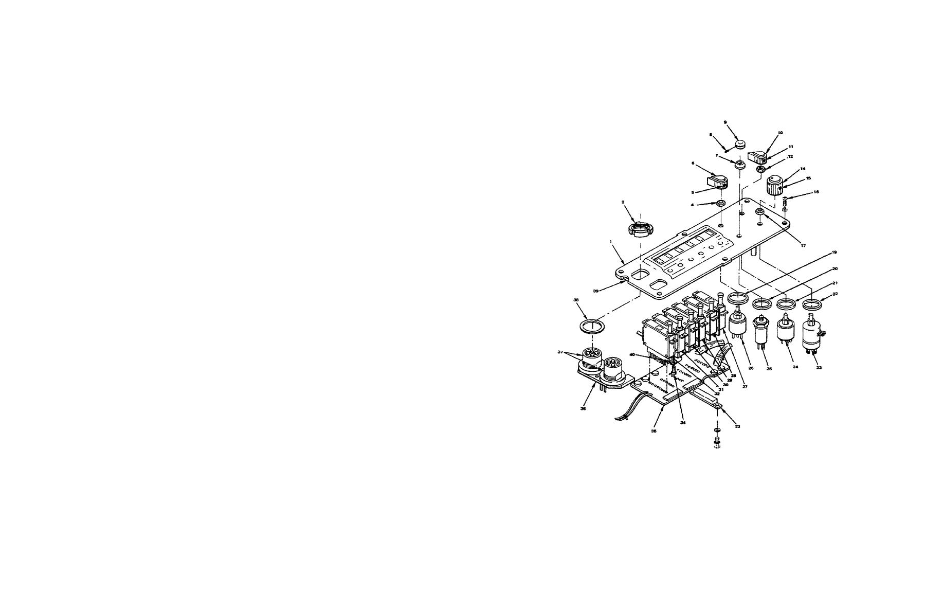
Figure 6-2. Control Panel A1A4 Component Location (Sheet 1 of 2) |
|
||
| ||||||||||
|
|  TM 11-5820-919-40-2
ITEM
DESCRIPTION
1.
Panel
2.
Connector Ring (2 places)
3.
Deleted
4.
Nut
5.
Allen Screw (2 places)
6.
SB Switch Knob
7.
Retainer (threaded)
8.
Allen Screw N
9.
Light switch Knob
10.
Mode Switch Knob
11.
Allen Screw (2 places)
12.
Nut
13.
Deleted
14.
Volume Knob
15.
Allen Screw (2 places)
16.
Screw, Captive (6 places)
17.
Nut
18.
Deleted
19.
Gasket
20.
Gasket
21.
Gasket
22.
Gasket
23.
Switch, Volume
24.
Switch, Mode
25.
Switch, Light
26.
Switch, Rotary SB
27.
100 Hz
28.
1 KHz
29.
10 KHz
30.
100 KHz
31.
1 MHz
32.
Switch, Rotary, 10 MHz
33.
Connector, Multipin A1A4J1
34.
Allen Screw (12 places)
35.
Circuit Board Assembly (Control Panel) A1A4A1
36.
Audio Filter Assembly A1A4A2
37.
Connectors A1A4A2J1 A1A4A2J2
38.
Connector Washer (2 places)
39.
Gasket
40.
Lockwasher (12 places)
Figure 6-2. Control Panel A1A4 Component Location (Sheet 1 of 2)
56
|
|
Privacy Statement - Press Release - Copyright Information. - Contact Us |
