 |
|||
|
|
|||
|
Page Title:
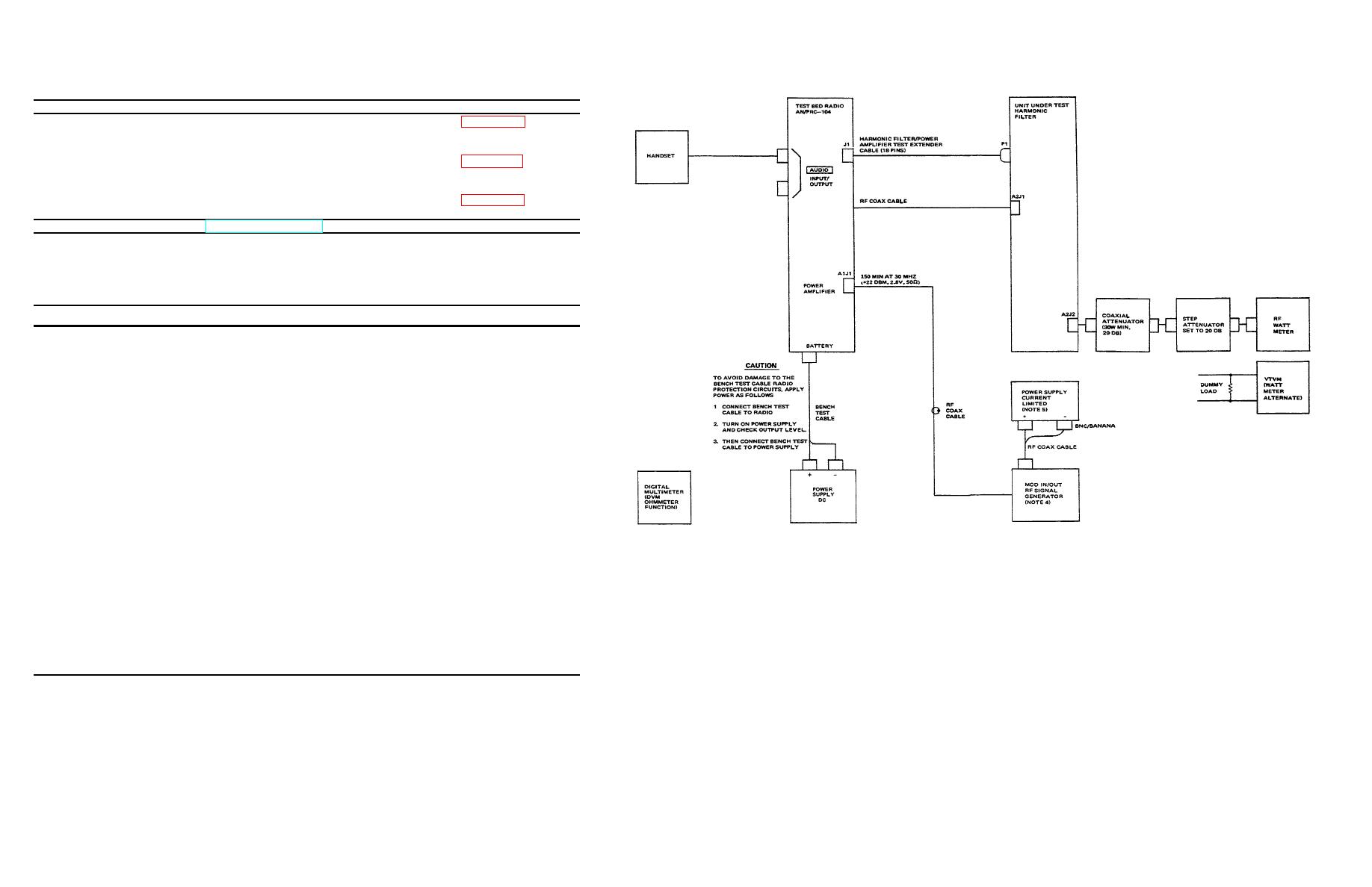
Figure 4-5. Harmonic Filter A1A2 Alignment Setup. |
|
||
| ||||||||||
|
|  TM 11-5820-919-40-2
SPECIAL TOOLS, MATERIALS, AND FABRICATED TEST CABLES AND FIXTURES
Description
Part Number Reference
Harmonic Filter/Power Amplifier Test
Extender Cable
of-40-1
RF Coax Cable (2 each)
of -40-1
RF Coax Cable ( 1 each)
of -40-1
NOTE: Referenced figures are in TM 11-5820-919-40-1.
TEST EQUIPMENT
Name Designation Quantity
Radio Set, Test Bed
AN/PRC-104
1
VTVM
AN/USM-116
1
Signal Generator, RF
AN/USM-323
1
Digital Multimeter
AN/USM-341
1
(DVK, ohmmeter function)
Dummy Load (50 ohm)
DA-553( )/4
1
Watt Meter
- Power Meter
Hewlett Packard HP-435A
1
- Thermocouple Power
Hewlett Packard HP-8482A
1
Sensor
Power Supply, DC
Hewlett Packard HP-6439B
1
NOTES:
Power Supply, Current
Hewlett Packard HP-6215A
1
1.
EQUIVALENT TEST EQUIPMENT MAY BE USED
Limited
2.
USE ONLY TEST EQUIPMENT THAT IS PROPERLY
Attenuator, Coaxial
Narda 765-20
1
CALIBRATED FAILURE TO DO SO MAY PROVIDE
ERRONEOUS OR MISLEADING PERFORMANCE
(20 db, 30w min., 50 ohm)
OR FAULT INDICATIONS
Attenuator, Step
CN1128/U
3.
IF ADEQUATE WATTMETER IS NOT AVAILABLE
SUBSTITUTE VTVM TERMINATED WITH DUMMY
LOAD P = E2/R WHERE R = 5O OHMS
4.
SET MODULATION MODE SWITCH TO AM, EXT,
DC, AND TURN LEVEL SWITCH TO COW POSITION
PRIOR TO CONNECTING D C CABLE TO MOD
Figure 4-5. Harmonic Filter A1A2 Alignment Setup.
IN/OUT CONNECTOR
5.
SET OUTPUT VOLTAGE TO +2 VOLTS D.C.
CAUTION DO NOT EXCEED +5VDC SET CURRENT
45
REGULATION TO MINIMUM REQUIRED TO
PERFORM ALIGNMENT
|
|
Privacy Statement - Press Release - Copyright Information. - Contact Us |
