 |
|||
|
|
|||
|
Page Title:
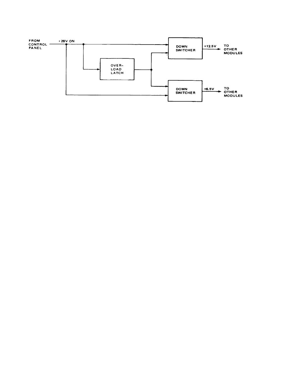
Figure 3-4. Power Supply Block Diagram |
|
||
| ||||||||||
|
|  TM 11-5820-919-12
Figure 3-4. Power Supply Block Diagram
shaft noticeable with temperature. The TCXO outputs
5MHZ LO goes to a frequency divider w here it is
3-32. The hydrid accepts signals from other modules in
divided to 10 KHz. The 1 kHz frequency is used by the
the radio set and generates the following alarm signals:
modulator/demodulator for cw key operation or for fault
(1) Low Battery Indicator (2) Tune In Progress and (3)
indication signals 3-29. The 5 MHz LO is also applied
Tune Fault. The Low Battery Indicator is set off if the
to a frequency multiplier which generates 70and 80MHz
+28v On from the control panel drops bellow +20v. The
harmonics. The harmonics are filtered by 70and 80-MHz
Tune In Progress indicates that the antenna tun er is
bandpass filters and routed to the limiter. The Sideband
automatically matching the antenna to the radio set at
Select signal is applied to the limiter. If the sideband
the selected frequency. The Alarm signal is routed from
select switch is set to LS B, then the limiter sends 80
the alarm circuits to the audio circuits to develop audible
MHz LO to the modulator/demodulator. If USB is
tones which ar e applied to the Rev Audio:
selected, the limiter sends 70 MHz LO to the
modulator/demodulator.
1. When battery power drops below +20v , a
clicking sound is heard in the handset.
2. If the antenna fails to complete a tune cycle
determines the output of the 77-105 MHz Lo signal
within 12 seconds. a repetitive beeping 1-kHz tone will
;using a dual phase -locked loop. A dual loop is faster
be heard in the handset (Tune Fault).
than a single loop phase locking system. A voltage
2.64 thru 9v) from the phase-locked loop tunes the
The tone will also be heard if a frequency below 2 MHz is
voltage-controlled oscillator (VCO) to a higher or lower
selected.
frequency.
The 77-105 MHz LO signal is divided in
the dual phase-locked loop ac cording to the Frequency
3. During the time that the antenna turner is in a
Select setting until it is 10 kHz. It is compared against
tune cycle. a steady, low-volume (I-kHz) tone is heard in
the 10 kHz from the frequency divider to provide the
the handset (Tune In Progress).
locking action. If the divided 77-105 MHz LO is above or
below 10 kHz.
the VCO's output is automatically
adjusted.
3-33. The audio circuits control the level of the transmit
signal and the gain of the receive signal . The mode
3-31. MNODULATOR/DEMODULATOR (Figure 3-6)
signal from the control panel inhibits transmit operation if
The
modulator/demodulator
performs
frequency
V_RCV is selected. the 1 KHz from the synthesizer is
conversion for both transmit and receive operation. The
switched on and off by the cw key. In transmit
audio control ;hydrid contains control circuits, while the
operation, the Xmt Audio Frequency is routed from the
three converters perform the frequency conversion. The
audio contro9l hydrid to the third converter, it mixes with
hydrid outputs the Xmt/Rev Control signal which
either 70 or 80 MHz, depending on the sideband
determines whether the racdxio0 set is in transmit or
selection (80 MHz for LSB,
70MHz for Usb
receive operation.
3-7
|
|
Privacy Statement - Press Release - Copyright Information. - Contact Us |
