|
| |
TM 11-5820-890-30-5
6-24.
Tools:
REPLACEMENT OF CONTROL-MONITOR
Flat tip screwdriver
Module extractor
References:
Paragraph
Paragraph
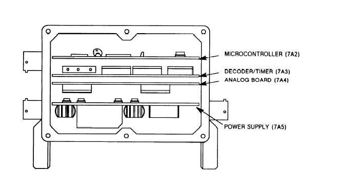
Figure 6-9
ITEM
6-20 for
6-22 for
Torque screwdriver
use of module extractor.
removal and installation of back cover.
for location of modules.
ACTION
REMARKS
REMOVAL
a. Back cover
b. Module
c. Module
INSTALLATION
d. Module
e. Module
Remove and retain.
Refer to paragraph 6-22
for removal procedures.
Hook module extractor to module using
Refer to paragraph 6-20 for
two holes in top corners of circuit card.
use of module extractor
and figure 6-9 for location
of modules
Pull free of control-monitor chassis.
Place module in card guides.
Press down to fully seat circuit card.
f. Back cover
Install on control-monitor chassis.
Refer to paragraph 6-22
for installation procedures.
Figure 6-9. Control-Monitor Module Locations.
6-48
|