|
| |
TM 11-5820-890-30-5
3-17. OPERATIONAL CHECK. Continued
Step 11. RF SECTION TEST.
CONNECT:
Signal generator output to UUT ANT connector,
and scope channel 1 input to RF DET connector
using mini probe tip adapter and X10 probe.
DISCONNECT: DMM.
NOTE:
If any RF SECTION TEST fails, check all internal RF cable, attenuator,
and relay connections for tightness prior to entering the appropriate
chart. If any connections are loose, tighten them and retest.
SET:
Signal generator:
Test adapter:
FREQ:
30 MHz
28 V: ON.
LEVEL:
0 dBm
MODULATION: OFF.
Action
a. Measure output of RF DET connector on
scope.
b. Set test adapter:
RF SWITCH: 1.
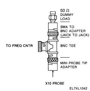
c. Connect scope channel 1 input to
FREQ CNTR connector using impedance
matching setup, shown below.
Response
a. Scope channel 1 displays a signal which
is 0 mV p-p (-10 to 10 mV p-p). If not,
go to chart 14.
b. Scope channel 1 displays a 560 to 700
mV p-p signal. If not, go to chart 15.
c. No response.
3-38
|