|
| |
TM 11-5820-890-20-2
1-41
1.13.
INTERCOMMUNICATION SET, AN/VIC 1(V). Continued
d.
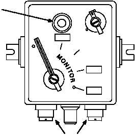
Control Box C 2297.
C 2297
OFF
EXT
SIG
J904
J901
AUDIO
ACCESSORY CONNECTORS
J903
J902
INDICATOR
LIGHT
VOLUME
C
B
ONLY
INT
A
ALL
(1) Circuit Description. The C 2297 is the driver's control box that is connected to the main junction
box. This control box has a MONITOR switch, VOLUME control, SIG EXT OFF switch, an indicator
lamp, and a microphone amplifier.
Power and control voltages used by the control box are applied to connector J904. Unlike the
C 2298 control box, the C 2297 cannot be connected in tandem.
Audio accessories are connected to J902 (RAD) or J903 (INT). Connector J902 is used to key a
radio. The radio cannot be keyed from connector J903. Pins A,B,D,and E of J902 and J903 are
wired in parallel. Audio signals for the intercom are applied to pins B and E of connectors J902 and
J903. EXT mic audio is applied unamplified to MONITOR switch.
(2) Functions of the MONITOR Switch Positions. Refer to Figure 1-4. The MONITOR switch is used
to select the audio and mic circuits to be connected to J902 and J903. The MONITOR switch can
select one of five positions. Positions •ALL" and •A" permit control of the bottom RT (RT A). Position
•C" permits control of the top RT (RT B).
When using a single radio mount the only position that can be used is the •ALL" position. The RT can
be keyed from the •A" and •B" positions, but not monitored.
(a) •ALL" Position. The •ALL" position provides for monitoring of the intercom, all RTs, and control of
the bottom RT (RT A). In the •ALL" position, the fixed audio output of all RTs and intercom are
applied to pin •L" of connector J904. From pin •L" of J904, the audio is applied to the MONITOR
switch. The audio leaves the MONITOR switch and is then applied to SIG EXT OFF switch and
VOLUME control. From the VOLUME control, the audio goes to pins B and E of J902 and J903.
Audio applied to the SIG EXT OFF switch is stopped when the switch is in the •OFF" position.
|