|
| |
TM 11-5820-890-20-2
1-38
1.13.
INTERCOMMUNICATION SET, AN/VIC 1(V). Continued
J504, J505, J506, or J507, pin F keys RT B. This PTT ground passes through the RADIO TRANS
and INSTALLATION switches and exits on J503, pin S. The control box must be set to the C
position.
(d) RT Transmit Audio. The amplified transmit audio for RT A or SRM enters J504, J505, J506, or
J507, pin K and exits J501, pin U. The control box setting is set to ALL or A for RT A or A for the
SRM.
The amplified transmit audio for RT B enters J504, J505, J506, or J507, pin V and exits J503, pin U.
The control box setting is C. When intercom is keyed, K502 energizes which cuts off transmit
audio.
c.
Control Box C 2298.
ALL
C 2298
J804
J801
J803
J802
AUDIO
ACCESSORY CONNECTORS
C
B
INT
ONLY
A
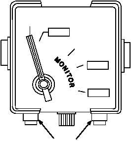
(1) Circuit Description. The C 2298/VRC is a control box connected to the main junction box. It has a
MONITOR switch, a VOLUME control, and a microphone (mic) amplifier. Power and control voltages
used by the control box are supplied through connectors J801 or J804. Multiple control boxes can
be connected in tandem.
Audio accessories are connected to connectors J802 (RAD) and J803 (INT). Pins A, B, D, and E of
J802 and J803 are wired in parallel. Pin C of J802 is used to key a radio. The radio cannot be keyed
from connector J803. Audio signals from the intercom or radio are applied to pins B and E of
connectors J802 and J803.
Audio signals from the mic are applied through pin D to the amplifier A80 and the main junction box
to the other control boxes or to the transmit (XMT) circuitry in the RT. The MONITOR switch is used
to select intercom or radio functions.
(2) Functions of the MONITOR Switch Positions. Refer to Figure 1-3. The MONITOR switch is used
to select the audio and mic circuits to be connected to J802 and J803. The MONITOR switch can
select one of five positions. Positions •ALL" and •A" permit control of the bottom RT (RT A). Position
•C" permits control of the top RT (RT B).
When using a single radio mount the only position that can be used is the •ALL" position.
|