|
| |
C 22 TO 32 V DC FROM RADIO
A
A
C
U
N
M
K
H
J505, J506, J507 (CREW)
J504 (COMMANDER)
J501
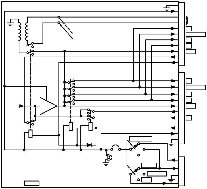
Figure 1-1. AM 1780/VRC DC P ower and Intercom Paths
AUDIO
E
TELEPHONE LINE
TO C 2297/VRC
INT ONLY
AUDIO
B
B
AUDIO
C
J
AUDIO
L
ALL
AUDIO
GROUND
22 TO 32 V DC
CREW'S INTERCOM MIC
A
M
A
AUDIO
K
C
V
COMMANDER'S INTERCOM
H
GROUND
E
INT ONLY
AUDIO
B
B
AUDIO
C
J
AUDIO
L
ALL
AUDIO
COMMANDER'S INTERCOM MIC
COMMANDER'S INTERCOM
C 22 TO 32 V DC
B VEHICLE POWER SOURCE
D
RELAY CONTROL LINE
TO RADIO
INT ONLY
OFF
NORM
MAIN PWR
A GROUND
K503
CR521
NOTES: 1)
CB501
ENERGIZED) ARE ENERGIZED WHEN
THE COMMANDER KEYS ON THE INTERCOM.
RELAYS K501, K502, K502 (SHOWN
2) RELAYS K501 AND K502 ARE ENERGIZED WHEN
CREW MEMBERS KEY ON THE INTERCOM.
3)
INDICATES EQUIPMENT MARKING.
DS501
A250
AMP
K502
K501
T501
E504
E503
TO FIELD
TELEPHONE
RECEIVED
RADIO
SIGNALS
CREW'S INTERCOM KEYING
MIC
KEYING
|