|
| |
TM 11-5820-890-20-2
1-31
1.12.
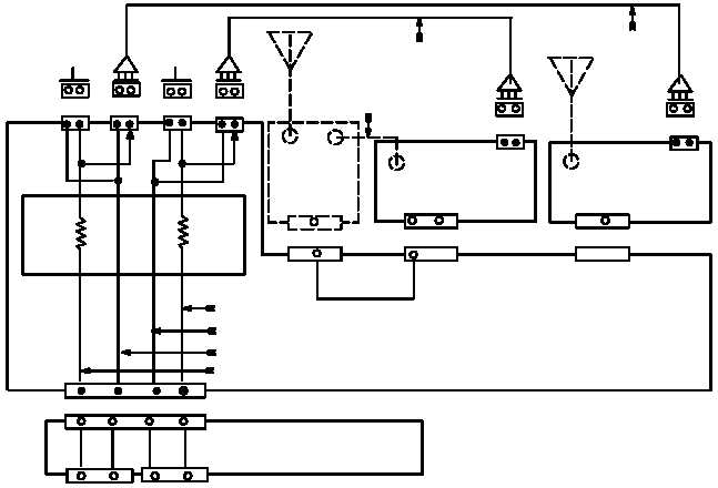
RADIO ANALOG TRANSMIT PATH.
a.
SINCGARS Radios Using the AM 7239 Series (VAA).
A= RT A or RCU A
B= RT B or RCU B
J5
J4
J3
POWER
AMPLIFIER
P1
P1
P1
J1
J8
J7
P1
W2
HANDSET
HANDSET
W4
W4
N
H
C D
C D
C D
C D
C D
C D
HI PWR XMIT
PTT
J2
J4
J3
J5
U
S
K
M
U
S
S
U
B TRANSMIT LINE
B KEYING LINE
A KEYING LINE
CABLE
CABLE
CABLE
AUD/DATA
AUD/DATA
A TRANSMIT LINE
•A"
•B"
MOUNTING BASE
VAA
24 K
24 K
The transmitter is •keyed" when the handset PTT switch is pressed. When the radio is mounted in a
vehicle, the handset is connected to the VAA.
A PTT command can also be generated by the LS 671 or VIC. MB connector J3 controls RT-A. MB
connector J4 controls RT-B.
Audio signals are generated in the handset when the PTT switch is pressed. These signals are passed
directly to the VAA connector J2 or J3. These connectors are wired in parallel to connectors J4 and J5,
and connector the the W4 cable. The audio is then passed on pin D to RT-A or RT-B.
Audio signals are generated at the loudspeaker control unit LS 671 or VIC. Cables pass these signals to
MB connector J3 or J4.
|