|
| |
TM 11-5820-890-20-2
1-27
1.10.
DC POWER INPUT AND DISTRIBUTION. Continued
d.
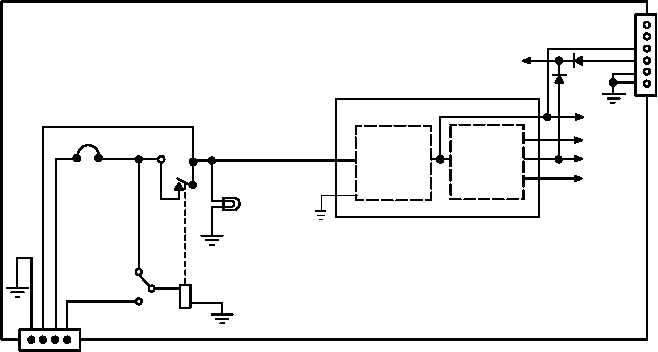
Power Distribution in Power Supply Adapter (PSA), MX 10862. The 22 to 32 V dc from J5, pin B, of
the MB enters the PSA through P1, pin B. P1, pin B is connected to CB1, which provides over current
protection for the power supply. In the MX 10862, a switch is used for local or remote mode. In local
mode the voltage present at P1, pin B either bypasses or energizes relay K1. In remote mode, the
voltage sent from a VIC or LS 671 to P1, pin E, energizes relay K1.
DS1 will light at the MX 10862 if power is present at the output contact of relay K1.
A
B
C
27 V DC
200 V DC
13 V DC
6.75 V DC
K1
CB1
DS1
P1
E
POWER SUPPLY A1
POWER SUPPLY ADAPTER
S1
(RMT)
(LCL)
B
F
C
E
D
A
J4
13 V DC to RT system
connector J2, pin F.
27 V DC
CR3
CR4
WARNING: ALL POWER SUPPLY VOLTAGES,
INCLUDING THE 200 V DC, ARE
PRESENT AT POWER SUPPLY
ADAPTER CONNECTOR J5.
MX 10862/VRC Power Distribution
RELAY CONTROL LINE
DC TO DC
CONVERTER
TRANSIENT
SUPPRESSOR
e.
Power Supply Module. The 22 to 32 V dc is applied to power supply A1. This power supply is a
dc to dc converter which takes the 22 to 32 V dc and produces the following voltages:
6.5
to
7.25 V dc
12.6
to
13.4 V dc
180.0
to
220.0 V dc
These voltages are used by RT A, RT B, RCU A, RCU B, control monitor, and PA installed on the VAA.
f.
Power Distribution in Battery Tray CY 8664/VRC. The CX 13290/VRC cable is used to connect PSA
connector J4 to battery tray connector J1. The 22 to 32 V dc present at PSA connector J4, pin F, is sent
through the cable to battery tray connector J1, pin F. This voltage energizes battery tray relay K1 to the
closed position. K1 will remain energized from 2 to 32 V dc. If the 13 V dc line from from the power
supply drops low, the MX 10862/VRC diodes allow the battery in the battery box connected to battery
tray connector P1 to provide the 13 V dc to the RT. The 13 V dc exits battery tray J1, pin E through the
cable to PSA connector J4, pin D. Pins E and A are ground at PSA connector J4. Pins D and A are
ground at battery tray connector J1.
A test switch is provided on the battery tray to test the battery voltage. If the test switch is pressed and
the battery is good, then DS1 lights. If the test switch is pressed and the battery is bad, the DS1 does
not light.
|