|
| |
TM 11-5820-890-20-2
8-4
8.2.
COMPONENT REPLACEMENT.
The following charts show by radio system component, those actions required to remove and install each
component. These charts cover all components of a short range , single radio mount system. Skip any
component that is not a part of the system being worked on. The component that needs to be replaced will be
identified by inspection, as noted above, or through application of the Operational Check and related
Troubleshooting Flowcharts. A general rule is to remove only those components that are required for
maintenance.
WARNING
REMOVE vehicular power from Mounting Base connector J1 before removing or replacing
components. If vehicular power is not removed, some connectors will have 22 to 32 V dc present.
In replacing an LS 671 Loudspeaker, disconnect cable from Mounting Base connector J3 or J4. If
cable is not disconnected, there will be 22 to 32 V dc present at pin B of the open cable
connector.
CAUTION
DO NOT under any circumstances remove component covers or remove modules from
components. Opening components in the field will destroy them.
DO NOT tilt or twist the RT/RCU when removing it from, or replacing it in, a power supply adapter
(PSA) to avoid damaging the connectors. The RT/RCU must be flat on the PSA when mating the
connectors.
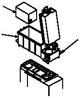
a.
Remote Control Unit (RCU) (Dismounted):
TO REMOVE:
TO REPLACE:
(1)
Set RCU FCTN to STBY
(1)
Position battery in battery box
(2)
Disconnect field fire from battery box terminal posts
(2)
Fasten two latches to secure battery box lid
(3)
Unfasten four battery box latches
(3)
Position battery box on RCU
(4)
Remove battery box
(4)
Fasten latches to secure four battery box to RCU
(5)
Unfasten two latches securing battery box lid
(5)
Connect field wire to battery box terminal posts
(6)
Remove battery
(6)
Set RCU FCTN to SQ ON
3
1
2
|