|
| |
TM 11-5820-890-20-2
1-20
1.8.
DESCRIPTION OF COMPONENTS. Continued
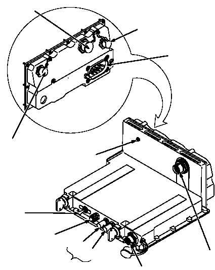
UNUSED CONNECTOR
(J5)
CONTROL MONITOR
CONNECTOR (J3)
REMOTE CONTROL
BINDING POSTS
SYSTEM
CONNECTOR (P1)
BATTERY TRAY
CONNECTOR (J4)
S1 SWITCH
(LCL/RMT)
E1
E2
DIMMABLE
LIGHT (DS1)
ON/OFF
SWITCH (CB1)
RT SYSTEM
CONNECTOR (J2)
TEST CONNECTOR
(J1)
ADAPTER, POWER SUPPLY MX 10862/VRC (PSA)
The Adapter, Power Supply MX 10862/VRC (PSA) will hold one RT and is used where space is such that the
VAA will not fit. The PSA mounts in the MB MT 6576/VRC. Switch S1 can be set to either LCL (LOCAL) or RMT
(REMOTE). The LCL setting turns system power on from the PSA CB1. The RMT setting allows the system to
be remotely powered from a LS 671/VRC or vehicular intercom. A CX 13314/VRC cable is needed to mate
connector J1 and the RT AUD/DATA connector for remote keying. Connector J1 also serves as a test connector
to aid in fault isolation.
The control monitor is connected to PSA connector J3. A battery tray, which provides RT back up power during
a system power failure, is connected to J4. Binding posts (E1 and E2) are present for the use of a remote
control unit.
|