|
| |
TM 11-5820-890-20-2
5-11
5.3.
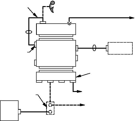
TROUBLESHOOTING FLOWCHARTS. Continued
NOTE
The following troubleshooting flowcharts are used with short range radio single
radio mount systems.
If the communications system includes a vehicular intercom VIC, begin
troubleshooting with chapter 2.
J3
J4
J2
J1
J1
J3
P1
J2
POWER SUPPLY
ADAPTER
RT
MOUNTING BASE
P1
J5
J1
J4
J5
AUD\DATA
To
22 32 V dc
PWR SOURCE
TO
ANTENNA
CG 3855 or CG 3856
CY 8664
BATTERY
TRAY
J4
CX 13314
IS PRESENT
ONLY IF A
LS 671
AND/OR VIC
IS PRESENT.
IF CABLE IS NOT
PRESENT
THEN HANDSET IS
PLACED AT
RT J4.
TEST
CONNECTOR
SHORT RANGE SINGLE RADIO MOUNT
CX 13290
MOUNTING BASE MAY BE EITHER
MT 6576 OR MT 6352 series
CX 13292
J1
RT
LS 671/
VRC
LOUD
SPEAKER
CX 13300
CX 13417
NOTE 2
TO VEHICLE
INTERCOM J501
NOTE 1
NOTE 1
NOTE
1. If the splitter cable (CX 13417) is not present, the loudspeaker cable (CX 13292) may be
connected directly to J3 or the vehicle intercom may be connected to J3 via the VIC
interface cable (CX 13313).
2. CX 13292 and CX 13300 may be connected to either mating connector of CX 13417.
|