|
| |
TM 11-5820-890-20-2
5-2
5.1.
THEORY OF OPERATION. Continued
H U S K A D C B
N U S P
A H U S K D C B
V F M K H
C
C A D
B
A C D
B
A E
B
D
+
-
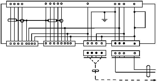
POWER CABLE
J5
J4
J3
J2
J1
TO PA MOUNT
OR SECOND RADIO
MOUNTING
BASE
(4) Power Supply Module. The filtered 22 to 32 V dc is applied to power supply A1. This power supply
is a dc to dc converter which takes the 22 to 32 V dc and produces the following voltages:
6.5 to 7.25 V dc
12.6 to 13.4 V dc
180.0 to 220.0 V dc
Input voltages less than 22 V dc will not harm the equipment. Voltages in excess of 35 V dc are
shunted to ground by the transient suppressor. All power supply output voltages (except the 27
V dc line) can withstand a short circuit up to 10 seconds. Prolonged short circuits (greater than
10 seconds) may damage the power supply. These voltages are used by RT, RCU,
control monitor, and battery tray.
All power supply voltages are present at power supply adapter connector J5. The CX 13291
cable connects at J5 to a power amplifier mount, however the voltage lines are disconnected.
The power amplifier mount contains a power supply and does not need these voltages.
|