Order this information in Print

Order this information on CD-ROM

Download in PDF Format


Click here to make tpub.com your Home Page

Page Title: TROUBLESHOOTING FLOWCHARTS. Continued
Back | Up | Next

Click here for a printable version

Google


Web
www.tpub.com

Home


Information Categories
.... Administration
Advancement
Aerographer
Automotive
Aviation
Combat
Construction
Diving
Draftsman
Engineering
Electronics
Food and Cooking
Math
Medical
Music
Nuclear Fundamentals
Photography
Religion
USMC
   
Products
  Educational CD-ROM's
Printed Manuals
Downloadable Books


TM  11-5820-890-20-2 2-162 2.2. TROUBLESHOOTING FLOWCHARTS. Continued Chart 43 NO RT MODULATION AT SRM FROM COMMANDER'S C 2298. (Sheet 11 of 12) NOTE: The CX 13313 and CX 13300 may be connected to either MB J3 or J4. These cables then connect to the AM 1780 connector J501. Connector J501 provides the dc power to the rest of the VIC system. V U T S R P N M L K J H F E D C B A CX 13313 P1 
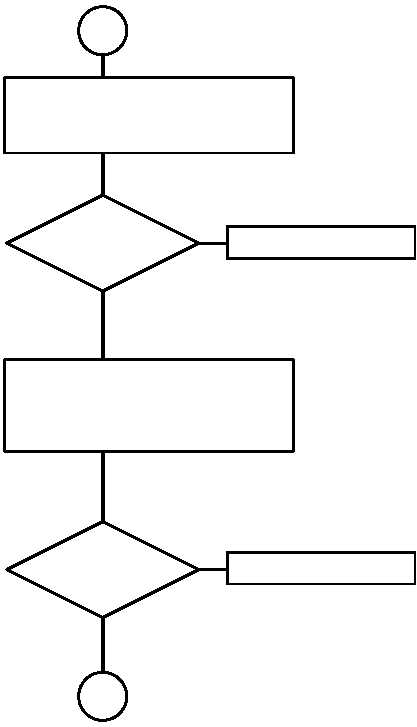
1.   CONNECT CX 13300 TO AM 1780 J501. 2.   REMOVE CX 13313 FROM CX 13300. 3.   CHECK CONTINUITY AT CX 13313 P1, PIN U TO PIN A (GND). NO YES SHORT TO GROUND ? REPLACE CX 13300. 13 SH 12 NO YES SHORT TO GROUND ? 1.   REMOVE RT. 2.   REMOVE PSA FROM MB. 3.   REMOVE CX 13313 FROM MB J3 OR J4. 4.   CHECK CONTINUITY AT CX 13313 P1, PIN U TO PIN A (GND). REPLACE CX 13313. 11 SH 11


Privacy Statement - Press Release - Copyright Information. - Contact Us - Support Integrated Publishing

Integrated Publishing, Inc. - A (SDVOSB) Service Disabled Veteran Owned Small Business