|
| |
TM 11-5820-890-20-2
2-150
2.2.
TROUBLESHOOTING FLOWCHARTS. Continued
Chart 42
SRM WILL NOT KEY FROM COMMANDER'S C 2298.
MONITOR SWITCH AT ALL POSITION.
(Sheet 3 of 4)
NOTE:
The CX 13313 and CX 13300 may
be connected to either MB J3 or
J4. These cables then connect to
the AM 1780 connector J501.
Connector J501 provides the dc
power to the rest of the VIC
system.
A
D
B
C
E
F
K
S
U
T
L
H
M
V
R
P
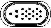
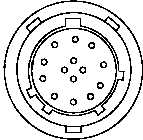
PSA P1
N
J
PSA J1
K
L
F
E
R
M
H
C
B
A
D
J
N
P
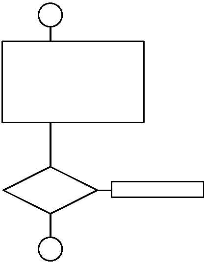
1. SET PSA CB1 TO OFF.
2. REMOVE CX 13314 CABLE FROM PSA J1,
AND RT.
3. REMOVE PSA FROM MB.
4. IF AM 1780 IS CONNECTED TO MB J3,
CHECK CONTINUITY AT PSA
J1, PIN E TO P1, PIN K.
5. IF AM 1780 IS CONNECTED TO MB J4,
CHECK CONTINUITY AT PSA
J1, PIN E TO P1, PIN S.
NO
YES
OPEN
?
REPLACE PSA.
3
SH 4
2
SH 3
|