 |
|||
|
|
|||
|
Page Title:
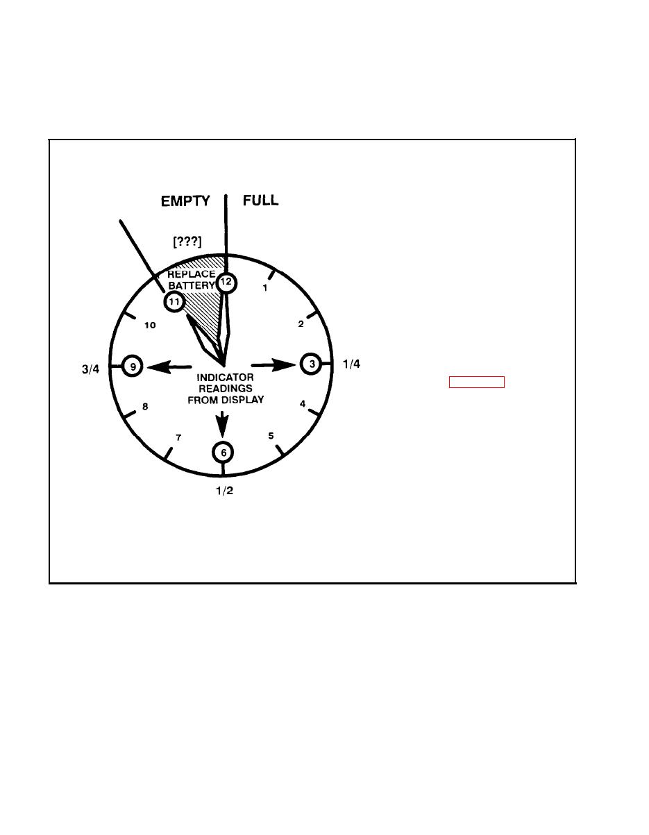
Figure 5-23. Battery Life Indicator Chart |
|
||
| ||||||||||
|
|  TM 11-5820-890-10-8
Remember also that in the absolute worst case where you lose main
WORST CASE
power and your HUB is dead, all you have to do is perform an ICOM fill,
including sync time, using your ANCD
The RT computes the
condition by
battery
measuring the time spent in
the receive and transmit
modes. Operating the RT in
receive m o d e f o r 2 1 0
minutes
increases
the
battery condition value by
one. Transmitting for 24
minutes also increases the
value by one. The battery
should be replaced when
the value is 11. The Battery
Life Indicator uses 12 to
indicate
the
power
exhaustion point, not hours.
For estimated hours of
battery life for different
uses, see Chapter 8. This
clock shows that for normal
(9:1 duty cycle) operations,
a reading of 3 means you
have used about 1/4 of your
battery, a reading of 6
means half the power has
been used up, 9 indicates it
is 3/4 gone, and 12
represents
exhaustion.
These are rough estimates
only, and they apply to
operators, not NCS or other
heavy radio users. A 6 could
mean power exhaustion for
a manpack NCS operator.
Figure 5-23. Battery Life Indicator Chart
5-66
|
|
Privacy Statement - Press Release - Copyright Information. - Contact Us |
