 |
|||
|
|
|||
|
Page Title:
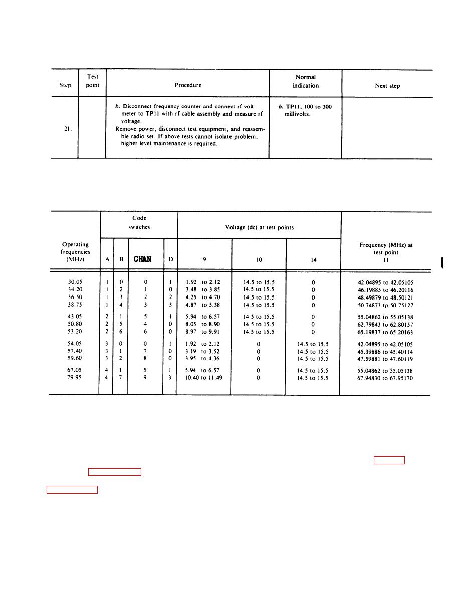
Table 3-4. Synthesizer Test Voltages and Frequencies |
|
||
| ||||||||||
|
|  TM 11-5820-882-23/TM 06827A-23/2
Table 3-3.
Fault Isolation Test--Continued
Table 3-4. Synthesizer Test Voltages and Frequencies
Section III.
MAINTENANCE PROCEDURES
3-10. Removal and Replacement of
(2) Inset corner of screwdriver tip into forward
.
Modules
(panel end) pry slot on converter module. Extend left
thumb over converter module to stop module travel and
The following procedures are used for removal and in-
pry up this end of the module (see fig. 3-10). Move
sertion of the modules in the Radio Set. The Special in-
screwdriver to other slot on the converter module and
structions in paragraph 3-11 should also be observed to
pry up. Remove module from radio with fingers.
prevent secondary damage and failures, Refer to
(3) To insert converter module, align module pins
with frame sockets and gently press module into place,
a. Converter Module.
b. I-f/A-f Module.
(1) Hold radio in left hand with control panel
(1) Hold radio in left hand with bottom side (bat-
toward palm, thumb over converter module and fingers
tery connector side) in palm and left thumb over i- f/a-f
over radio on opposite side.
module and fingers on back side of radio.
Change 1
3-15
|
|
Privacy Statement - Press Release - Copyright Information. - Contact Us |
