 |
|||
|
|
|||
|
Page Title:
Section II. SERVICE UPON RECEIPT |
|
||
| ||||||||||
|
|  TM 11-5820-882-23/TM 06827A-23/2
Section II. SERVICE UPON RECEIPT
2-4. Checking Unpacked Equipment
minals.
c. Remove module cover by turning the two captive
a. Inspect the equipment for damage incurred dur-
screws counterclockwise (located on bottom of module
ing shipment. If the equipment has been damaged,
cover).
report the damage on DD Form 6, Packaging Improve-
NOTE
ment Report.
b. Check the equipment against the packing slip to
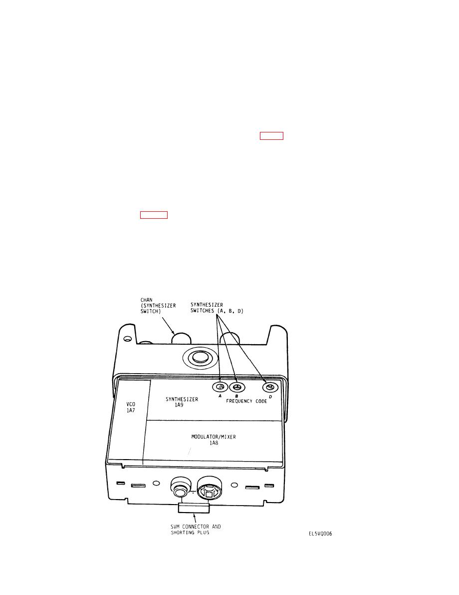
Make sure that the svm shorting plug (located
see if the shipment is complete. Report all discrepancies
next to the battery terminal connector in the rt
in accordance with the instructions of TM 38-750.
unit, fig. 22), is installed and in good condi-
Marine Corps units should refer to current edition of
tion. The radio set will not work unless the
TM 4700-15/1.
shorting plug or svm is installed.
c. Check DA PAM 310-7 to see whether there are
2-6. Reassembly Instructions
any modification work orders pertaining to this equip-
ment.
To reassemble the radio set, perform the following:
a. Apply a thin coat of silicone grease (NSN 6850-
00-177-5094) to top edge of the module cover. Slide
To disassemble the radio set for battery replacement or
module cover over rt unit and secure with the two cap-
channel changing and alignment (fig, 1-2), perform the
tive screws located on the bottom of the cover (turn
following:
clockwise),
a. Unfasten latches on battery case and remove bat-
b. Attach battery to battery connector on rt unit,
tery case. (Handle case carefully as damaged case will
c. Apply a thin coat of silicone grease to the top edge
not seal properly).
of the battery case and attach battery case and secure
with the two latches,
b. Remove battery by disconnecting snap ter-
Figure 2-2. Radio set component locations, rear view.
2-2
|
|
Privacy Statement - Press Release - Copyright Information. - Contact Us |
