 |
|||
|
|
|||
|
Page Title:
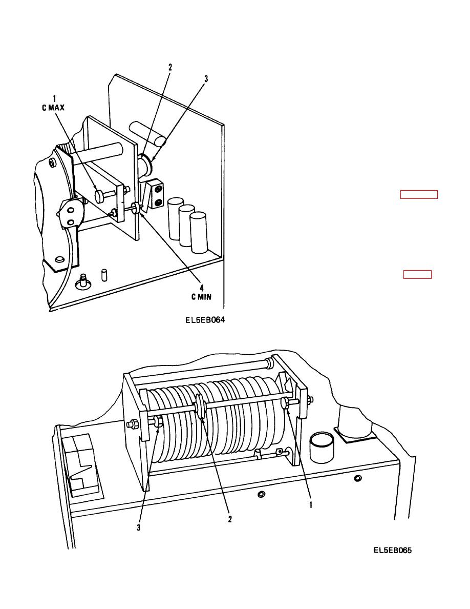
Figure 4-18. CMAX/C MIN Adjustment Locator |
|
||
| ||||||||||
|
|  TM 11-5820-873-34
of the coil wire. It should be between 1/4 and S/4 inch.
If not, move roller (2) away from plunger and adjust
plunger length as necessary. Repeat steps 2 and 3 until
adjustment is within tolerance.
(4)
Connect multimeter between L MIN
plunger (1) and chassis ground. Rotate inductor to
move roller (2) in contact with L MIN plunger. Stop
when roller/plunger contact causes meter to indicate a
short.
(5)
Check the distance from the roller to
the end of the coil wire. It should be between 1/ and /4
inch. If not, move roller (2) away from plunger and
adjust plunger length as necessary. Repeat steps 4 and
5 until adjustment is within tolerance. Reinstall antenna
coupler in case.
c.
Amplitude Detector Adjustment. (Fig 4-20)
(1)
Remove case from Antenna Coupler
CU2229/URC-92.
Connect RF and control cables
between the Antenna Coupler and Receiver/Transmitter
RT-1277/URC-92. Ensure the receiver/transmitter is
correctly powered and grounded.
(2)
Loosen fasteners and swing Phase
and Amplitude Control CCA away from chassis.
Disconnect and isolate RF line from terminal post (1).
Connect clip leads of a BNC/clip lead cable (fig 4-1) to
terminal post (1) and ground post (2) Connect a 50 ohm
dummy load to BNC/clip lead cable.
NOTE
Cable clip leads should not exceed 1
inch in length. Overall cable length
should not exceed 6 inches.
Figure 4-18. CMAX/C MIN Adjustment Locator
Figure 4-19 LMAX/L MIN Adjustment Locator
4-45
|
|
Privacy Statement - Press Release - Copyright Information. - Contact Us |
