 |
|||
|
|
|||
|
Page Title:
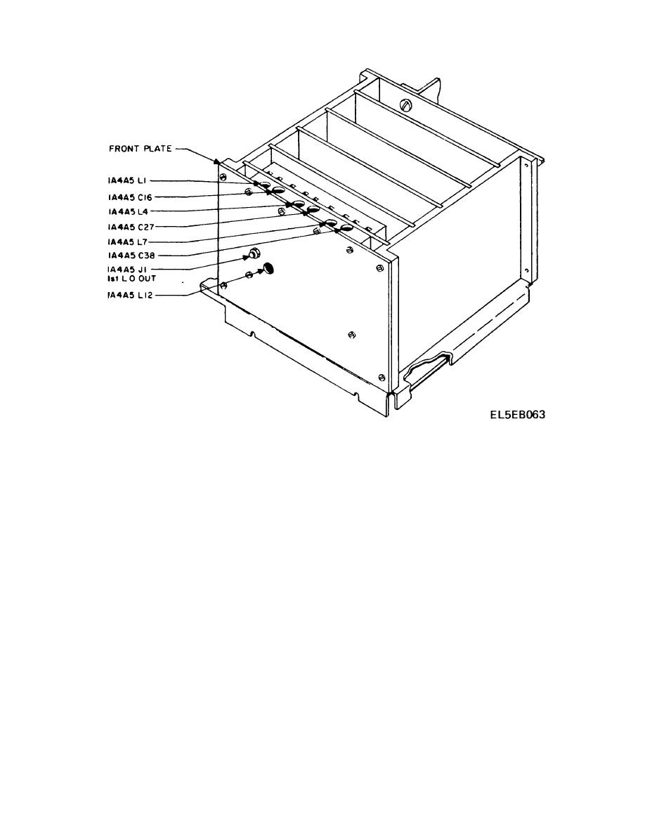
Figure 4-17. VHF VCO CCA Adjustment Points |
|
||
| ||||||||||
|
|  TM 11-5820-873-34
Figure 4-17. VHF VCO CCA Adjustment Points
1. Set front panel 1 MHz frequency selector to 0 Adjust
Inject + 1.95 VDC, from a bench power supply, at
1A4A5L4 for 101.75 0.2 MHz.
1A4A5-4. Connect a 47 ohm, 1/2 or 1/4 watt, resistor
(c) Set front panel 1 MHz frequency selector
between 1A4A5-2 and ground.
only to 9 Adjust 1A4A5C27 for 110.75 0.75 MHz.
(b) Set front panel 10 MHz frequency
(d) Repeat step (b) and (c) above until both
selector to 1. Set front panel 1 MHz frequency selector
frequency
adjustments
are
within
tolerance
to 6. Adjust 1A4A5L12 for approximately 225 mV RMS.
simultaneously.
Minimum acceptable output is 100 mV RMS.
(4) Band "2" Adjustment
(c) Record VTVM reading 1 MHz frequency
(a) Connect frequency counter to 1st Local
selector set to 0. Record RF voltmeter reading with 10
Oscillator output 1A4A5J1. Inject + 1.95 VDC, from a
MHz frequency selector set to 2 and 1 MHz frequency
bench power supply, at 1A4A5-4.
selector set to 9.
(b) Set front panel 10 MHz frequency
(d) Readjust 1A4A5L12 as necessary so the
selector to 2. Set front panel 1 MHz frequency selector
VTVM readings are within 3 dB of each other in steps
to 0. Adjust 1A4A5L7 for 111.75 0.2 MHz
(b) and (c) above.
(c) Set front panel 1 MHz frequency selector
(e) Remove 47 ohm resistor between
only, to 9 Adjust 1A4A5C38 for 120.75 0.75 MHz.
1A4A5-2 and ground.
(d) Repeat steps (b) and (c) above until both
(6) Remove dummy load.
Reinstall VHF
frequency
adjustments
are
within
tolerance
Divider CCA 1A4A4. Reinstall Synthesizer protective
simultaneously.
cover.
Reinstall receiver-transmitter bottom cover.
(5) 1st Local Oscillator Output Level
Reinstall receiver-transmitter top cover. Reinstall front
(a) Connect VTVM (AC) (w/50 ohm
panel.
termination) to 1st Local Oscillator output 1A4A5-J1.
4-43
|
|
Privacy Statement - Press Release - Copyright Information. - Contact Us |
