 |
|||
|
|
|||
|
Page Title:
Figure 4-11. 19.45 MHz Adjustment Setup #3 (1A4A3) |
|
||
| ||||||||||
|
|  TM 11-5820-873-34
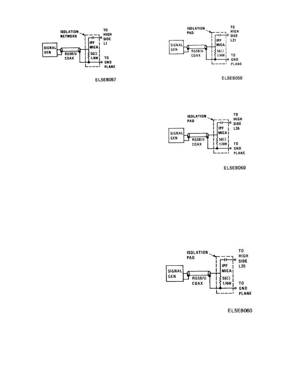
Figure 4-12. 100.75 MHz Bandpass Filter Adjustment
Figure 4-11. 19.45 MHz Adjustment Setup #3 (1A4A3)
Setup #1
NOTE
(b) Adjust 1A4A3L21 for maximum output.
The following adjustment involves three
(c) Connect signal generator as shown in
interacting components Due to this
Figure 4-13. Frequency setting remains at 100.75 MHz.
interaction
the
adjustment
of
each
component should be repeated until
maximum output is obtained
NOTE
As adjustment progresses in the following
step, reduce signal generator output level to
maintain VTVM indication below 100 mV
RMS.
(f) Adjust 1A4A3L1, then 1A4A3L2 and then
1A4A3L3 for maximum VTVM Indication.
(g) Remove Isolation pad connected between
L1 and ground Remove jumper from 1A4A3U1-2.
Figure 4-13. 100.75 MHz Bandpass Filter Adjustment
Reinstall Low Digit Generator CCA 1A4A2 Connect VTVM
Setup #2
(AC) between 1A4A3U3-1 and ground Connect RF
NOTE
voltmeter to 1A4A3-TP1 using a 50 ohm termination.
The following adjustment involves two
NOTE
interacting components.
Due to this
The following adjustment involves four
Interaction
the
adjustment
of
each
interacting components Due to this
component should be repeated until
interaction
the
adjustment
of
each
maximum output is obtained.
component should be repeated until
(d) Adjust 1A4A3L36 and then L21 for
maximum output is obtained.
maximum VTVM indication.
(h) Carefully readjust L1, L2, L3, and L5 for
(e) Connect signal generator as shown in
maximum VTVM indication.
Figure 4-14. Frequency setting remains at 100.75 MHz.
(5) 2nd Local Oscillator Adjustment
(a) Connect oscilloscope to 1A4A3-11.
Ground scope to CCA ground Connect frequency counter
to oscilloscope vertical amplitude output.
(b) Adjust 1A4A3L25 to approximately the
midpoint of its adjustment range. Adjust 1A4A3L17 for
80.75 MHz. Readjust L25 for maximum output Minimum
acceptable output is 300 mV peak-to-peak at 80.75 MHz
4 KHz.
(6) 100 75 MHz Bandpass Filter Adjustment
(1A4A3).
(a) Jumper junction of 1A4A3Q8 gate #1 and
R70 to CCA ground. Connect VTVM (AC) (w/50 ohm
termination) to 1A4A3-TP3 Using frequency counter set
signal generator to 100.75 MHz.
Connect signal
Figure 4-14. 100.75 MHz Bandpass Adjustment Setup
generator as shown in Figure 4-12.
#3
4-41
|
|
Privacy Statement - Press Release - Copyright Information. - Contact Us |
