 |
|||
|
|
|||
|
Page Title:
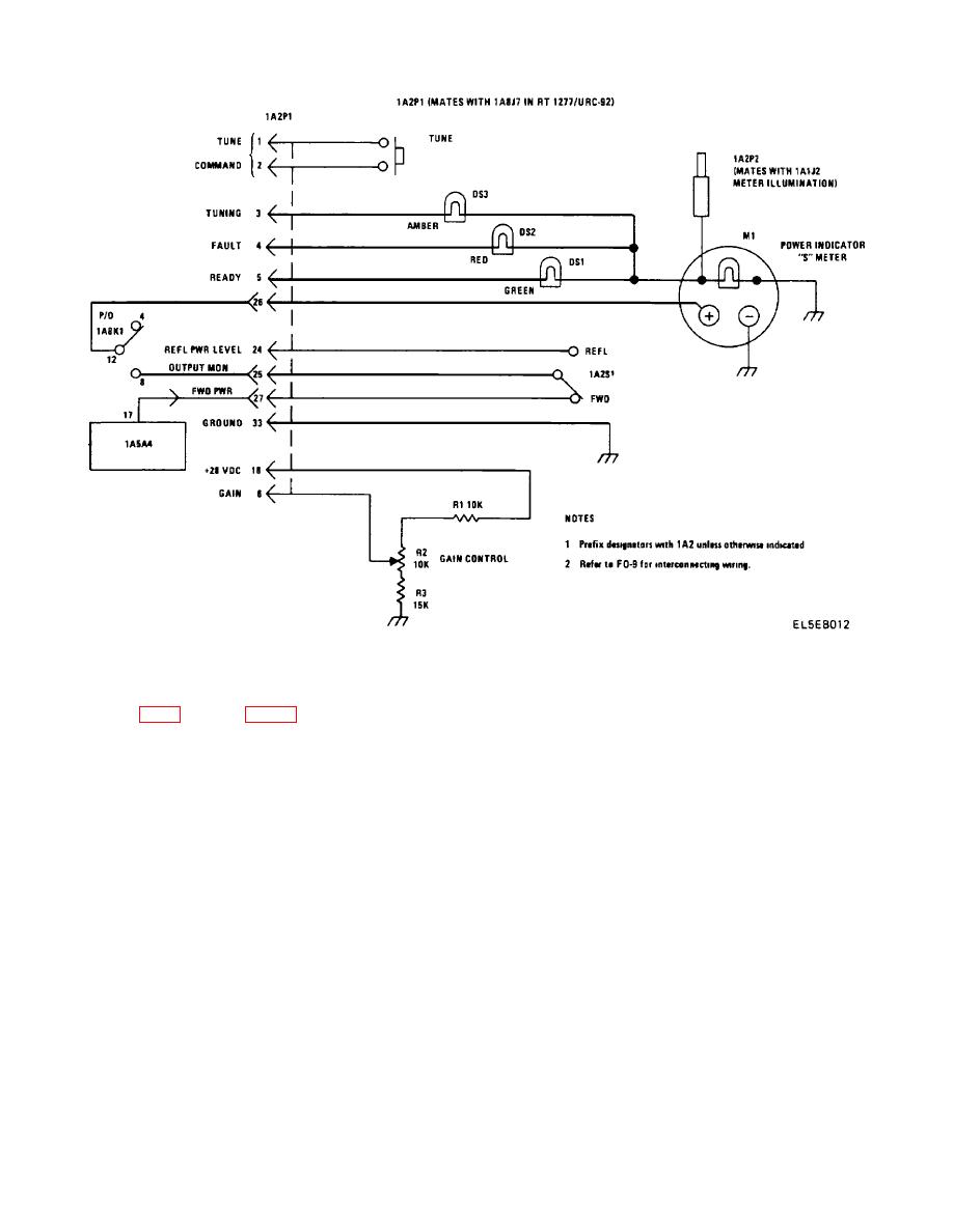
Figure 2-4. Antenna Coupler Control Unit Schematic Diagram. |
|
||
| ||||||||||
|
|  TM 11-5820-873-34
Figure 2-4. Antenna Coupler Control Unit Schematic Diagram.
board 2A4.
Board 2A4 develops phase (2A4-2),
2-13. Detailed Theory of Operation
amplitude (2A4-5) and reflected power (2A4-3) error
signals. Each of these error signals is referenced to the
To begin a tune cycle, the RT-1277/URC-92 mode
10 volt line. The reflected power signal goes to control
switch must be set to CPLR TUNE KW. The CPLR
logic board 2A1 pin 15. It is used as a control signal for
TUNE KW position provides the ground necessary to
many AN/URC-92 operations. Phase error between
energize relay 2K1. When 2K1 is energized, +28 VDC
2A2-2 and 2A2-3 is processed and a corrective drive
(CPLR tune +) is present at one side of the antenna
signal is produced. The home drive is removed and the
coupler control TUNE START switch. Depressing TUNE
corrective drive takes over as soon as the phase
start returns the +28 VDC (CPLR tune + R) to the
becomes positive. The corrective drive signal for phase
antenna coupler control logic board 2A1 pin A. The +28
occurs at either 2A2-4 or 2A2-5 depending upon the 2C1
VDC at 2A1-A generates a keying signal at 2A1-7, a
adjustment necessary. Amplitude error between 2A2-16
2C1 home pulse at 2A1-13 and a 2L4 home pulse at
and 2A2-U is processed and a corrective drive signal
2A1-R. A ground is supplied, by 2A1-6, to 1A2-3 which
produced for 2L4 adjustment. Again the home drive
lights the COUPLER STATUS TUNING indicator. Also,
signal is removed and the corrective drives takes over,
a ground is present at 2A1-15 which energizes 2K4.
at either 2A2-17 or 2A2-V, when the phase goes
Normally 2K4-9, 1 with 2K4-10, 2 shunt the RF around
positive. The phase and amplitude corrective drive
the 3 dB attenuator.
In a tune cycle, with 2K4
signals oscillate until 2C1 and 2L4 are tuned to
energized, the 3 dB attenuator is placed in series in the
minimum reflected power. At that point, 2A2 causes a
RF line. The 2A1 home pulses enter the phase and
motor braking action at 2A2-T and 2A212. The servo
amplitude control board 2A2 on pin 6 for 2C1 and pin R
motor control (2A6) receives the drive signals from 2A2
for 2L4. The home pulses set 2A2 flip-flops to provide a
and amplifies them to drive 2M1 and 2M2 as necessary.
homing signal at 2A2-5 for 2C1 and at 2A2-V for 2L4.
Motors 2M1 and 2M2 then adjust 2C1 and 21L4
Simultaneously, the transceiver produces an RF output
that is sensed in the phase and amplitude detector
2-16
|
|
Privacy Statement - Press Release - Copyright Information. - Contact Us |
