 |
|||
|
|
|||
|
Page Title:
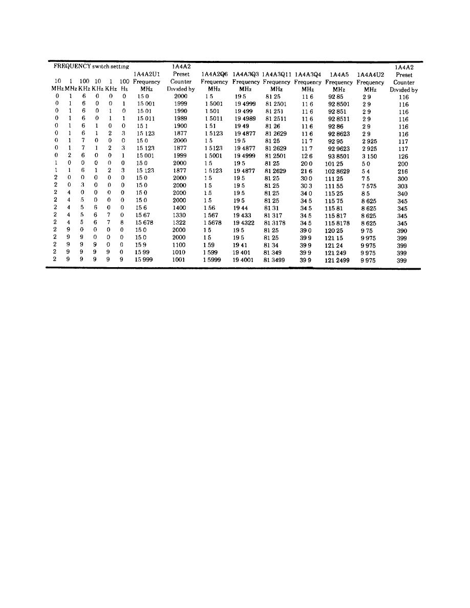
Table 2-1. Synthesizer Programmed Frequencies. |
|
||
| ||||||||||
|
|  TM 11-5820-873-34
Table 2-1. Synthesizer Programmed Frequencies.
generator ((2) above) is 1.877 MHz (the difference
diodes 1A4A2CR3, 1A4A2CR4 as a fine steering
between the VCO frequency and the 17 MHz reference
voltage. Transistor 1A4A2Q1 is the oscillator while
signal. And, the preset counter will divide by 1,877.
1A4A2Q2 regulates the source voltage in order to
The output from the preset counter will be a 1 kHz
provide frequency stability. The output from the VCO is
pulse. The operation of the preset counter is as follows:
coupled through buffer 1A4A2U1 to mixer 1A4A2Q3 ((2)
(a) Assuming the selected 10 kHz, 1 kHz and
below) and driver 1A4A2Q5 ((5) below).
(2) Mixer and Pulse Generator. The 15.0 to
100 Hz FREQUENCY switches are set to 1, 2 and 3
respectively, 1A4A2U8 will have the binary coded
15.999 MHz signal from the VCO ((1) above) is applied
decimal equivalent of three present at the preset input;
to mixer 1A4A2Q3. The other input to the mixer is the
1A4A2U9 will have the binary coded decimal equivalent
17 MHz reference signal from spectrum generator
of two present at the preset input; and 1A4A2U10 will
1A4A1 (a above). The 1.001 to 2.0 MHz difference
have the binary coded decimal equivalent of one
frequency output from 1A4A2Q3 is filtered by the 2 MHz
present at the preset input. When a data strobe pulse is
low pass filter and amplified by 1A4A2U6.
The
received from preset generator 1A4A2U4, the divide-by-
sinewave output from 1A4A2U6 is formed into pulses by
10 counters are preset to the count that is present at
pulse generator 1A4A2U7 The output from 1A4A2U7 is
their preset inputs.
applied to the inputs of the preset counter and the count
(b) Divide-by-10 counter 1A4A2U8 has been
filled detector ((3) below).
preset to a count of three ((a) above). The output at pin
(3) Preset Counter and Preset Generator. The
5 is high and the output at pin 12 is low. The output at
preset counter consists of three divide-by-10 counters
pin 5 will be high for each odd count and low for each
(1A4A2U8, 1A4A2U9 and 1A4A2U10) and one divide-
even count. The divide-by-10 counter will count on the
by-2 counter 1A4A2U11). With the selected 10 kHz, 1
trailing edge of each input pulse. After six input pulses,
kHz and 100 Hz FREQUENCY switches set to 000, the
the count in 1A4A2U8 will be nine (preset of three, plus
preset counter is divide-by-2000 counter. With the
six counts). At the count of nine, the output at pin 12
selected 10 kHz, 1 kHz and 100 HZ FREQUENCY
will be high because of the nine count and the output at
switches set to a value other than 000, the counter will
pin 5 will be high because the count is an odd number.
divide by 2000 minus the value set by the switches. If
On the trailing edge of the next input pulse, the outputs
the selected 10 kHz, 1 kHz and 100 Hz FREQUENCY
at pins 5 and 12 will both go low. When pin 12 goes
switches are set to 1, 2 and 3 respectively, the output
low, 1A4A2U9 will advance one count. On the trailing
frequency of VCO 1A4A2Q1 ((1) above) is 15 123 MHz
edge of the next input pulse from pulse generator
(the setting of the selected FREQUENCY switches times
10, plus 15 MHz). The output of the mixer and pulse
2-11
|
|
Privacy Statement - Press Release - Copyright Information. - Contact Us |
