 |
|||
|
|
|||
|
Page Title:
Power Supply 1A6 Functional Operation |
|
||
| ||||||||||
|
|  TM 11-5820-873-34
and the reference frequencies needed in the
2-7.
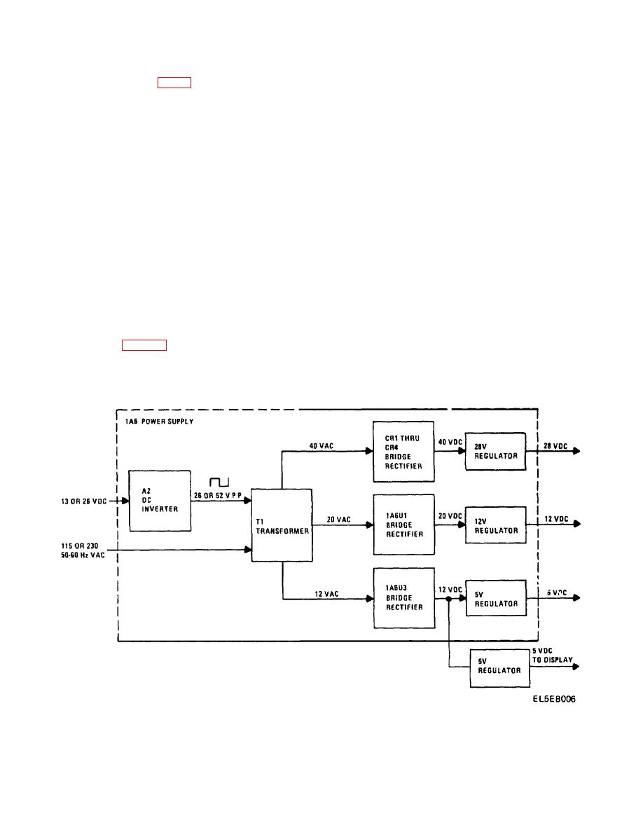
Power Supply 1A6 Functional Operation
synthesizer. All of the frequencies generated by the
(Fig. 2-2 and Fig. FO-31)
spectrum generator are derived by a combination of
a. The power supply provides regulated DC
multiplying, dividing and/or mixing the 5 MHz reference
voltages to operate the circuits in the RT-1277/URC-92.
signal from TCXO 1A8U1. The outputs from the
The input to the power supply can be from 115 or 230
spectrum generator are the 10.5 MHz, 3rd local
volt, 50 to 60 Hz AC power sources or from 13 or 26 volt
oscillator signal, 17 MHz and 1 kHz signals that are
DC power sources.
coupled to low digit generator 1A4A2, 20 and 21 MHz
b. When operated from a DC power source, the
signals that are coupled to translator 1A4A3 and a 100
input DC is applied to DC inverter 1A6A2. The DC
kHz signal that is coupled to VHF divider 1A4A4.
inverter converts the DC input to a 120 to 200 Hz square
b. Low Digit Generator 1A4A2.
The low digit
wave which is applied to primary 2 of transformer
generator controls the 10 kHz, 1 kHz and 100 Hz
1A6T1. When operated from an AC power source, the
components of the radios operating frequency. The
input AC is applied directly to primary 1 of transformer
inputs to the low digit generator are 17 MHz and 1 kHz
1A6T1.
signals from the spectrum generator, binary coded
decimal from the selected to 10 kHz, 1 kHz and 100 Hz
of 40 VAC, 20 VAC and 12 VAC. The secondary
FREQUENCY switches and a coarse steering voltage
outputs are applied through bridge rectifiers to the
from the 10 kHz FREQUENCY switch. The output is a
regulator circuits. The 28, 12 and 5 volt outputs from
1.5 to 1.5999 MHz signal with the frequency of the
the regulator circuits are used to operate the circuits In
signal being equal to 1.5 MHz plus the frequency set by
the radio.
the selected 10 kHz, 1 kHz and 100 Hz FREQUENCY
switches.
2-8.
Synthesizer
1A4
Simplified
Functional
c. Translator 1A4A3. The translator generates the
Operation (Fig. 2-3).
80.75 MHz, 2nd local oscillator frequency.
The
translator also combines the 80.75 MHz signal with the
20 MHz signal from spectrum generator 1A4A1, the 21
a. Spectrum Generator 1A4A1.
The spectrum
MHz signal from spectrum generator 1A4A1 (or from
generator generates the 3rd local oscillator frequency
2-8
|
|
Privacy Statement - Press Release - Copyright Information. - Contact Us |
