 |
|||
|
|
|||
|
Page Title:
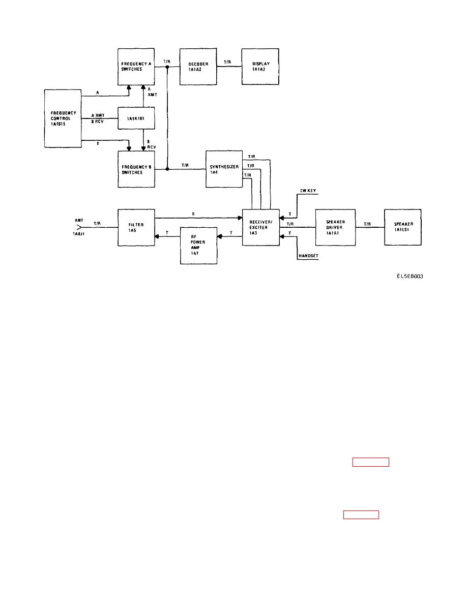
Figure 2-1. Radio Receiver-Transmitter Simplified Block Diagram. |
|
||
| ||||||||||
|
|  TM 11-5820-873-34
Figure 2-1. Radio Receiver-Transmitter Simplified Block Diagram.
fed to a 600 ohm line driver and to a fixed audio
oscillator signal from synthesizer 1A4. The resultant
amplifier. The envelope detector detects the amplitude
signal is filtered m a narrow band filter which passes
of the received signal reproducing the audio on a
only the 91.25 MHz 15 kHz portion of the signal. The
nd
transmitted AM signal. The resultant audio is also fed to
output from the filter is amplified and mixed with the 2
the 600 ohm line driver and to the fixed audio amplifier.
local oscillator signal from synthesizer 1A4, to produce
The output of the fixed audio amplifier is connected to
10.5 MHz. The 10.5 MHz output form the VHF mixer is
the VOLUME control, then to the speaker driver (located
coupled into IF filter 1A3A2. The IF filter amplifies the
on the front panel), which supplies up to five watts of
signal and it is fed to a diode gating network The diode
audio to the speaker. The AGC voltage is also used to
gating network selects the upper sideband filter (USB),
vary the current through the front panel meter to give a
lower sideband filter (LSB), or amplitude modulation
visual indication of relative signal strength received.
filter (AM) in accordance with the setting of the mode
switch. These filters determine the receiver's bandwidth
The front panel RF GAIN control acts to vary the gain of
and reduce the interference form adjacent channels The
an amplifier which reduces the AGC voltage, reducing
the gain of the RF amplifier and the IF amplifiers. This
upper sideband, lower sideband, or double sideband
greatly reduces background noise when receiving strong
output from the filters is further amplified and coupled
signals.
into audio board 1A3A4 where it is detected and
b. Detailed Functional Operation.
amplified In the audio board the signal is coupled to a
product detector when receiving sideband signals and to
(1) Power supply 1A6 (para 2-7) provides the
a fixed amplifier and an envelope detector for receiving
regulated DC voltages required to operate the circuits in
amplitude modulated signals. The fixed amplifier also
the RT-1277/URC-92.
feeds into the AGC detector which develops a DC
(2) TCXO 1A8U1 is an extremely stable,
voltage proportional to the received signal amplitude.
temperature controlled, crystal oscillator and provides
The AGC voltage is amplified and used to control the
the 5 MHz reference signal to the synthesizer.
voltage gain of the RF amplifier and the IF amplifiers.
(3) Synthesizer 1A4 (para 2-8) generates three
The product detector combines the signal with the 3rd
local oscillator frequencies The 1st local oscillator
local oscillator (10.5 MHz), giving an audio signal which
frequency of 91.25 to 121.2499 MHz is controlled by the
reproduces the original transmitted audio. The audio is
2-2
|
|
Privacy Statement - Press Release - Copyright Information. - Contact Us |
