 |
|||
|
|
|||
|
Page Title:
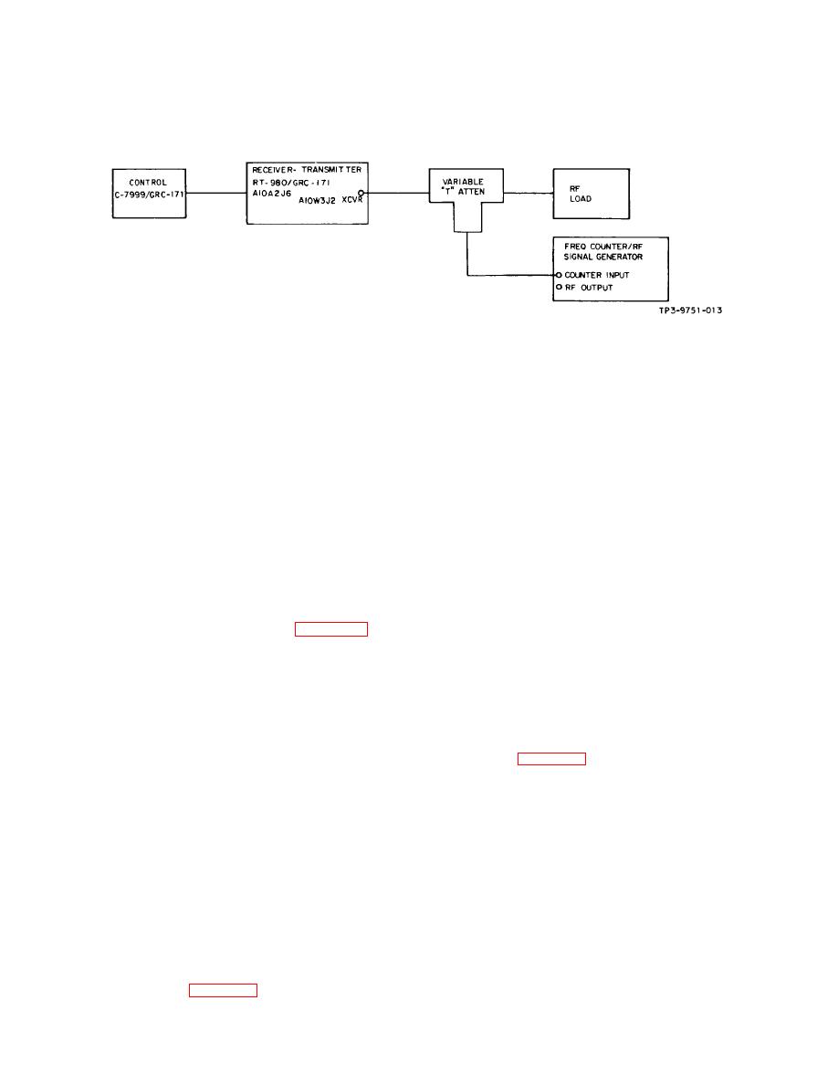
Figure 5-8. Test Setup for Radio Set Control C-7999/GRC-171 |
|
||
| ||||||||||
|
|  TO 31R2-2GRC171-2
TM 11-5820-815-14
NAVELEX 0967-LP-544-5010
Figure 5-8. Test Setup for Radio Set Control C-7999/GRC-171
a. Connect distortion analyzer and 600-ohm load
5-9.
VOLTAGE REQUIREMENTS AND SOURCES.
across the RT-980/GRC-171 main audio output.
5-10. Radio Set AN/GRC-171 and test equipment
require 120-V ac, 60-Hz, single-phase power for
b. Set the rf signal generator for rf output level of 2
operation.
to 2.5 V at 300.000 MHz, 30 percent modulation at 1
kHz.
5-11.
ALIGNMENT.
c. Set the RT-980/GRC-171 REMOTE/LOCAL
5-12. No alignment is required at the organizational/
switch to LOCAL, PTT/CARRIER TEST switch to PTT,
intermediate maintenance level. Alignment is performed
SQUELCH switch to ON, and frequency switches to
at the module level and is covered in section H.
300.000 MHz.
d. Set distortion analyzer FUNCTION control to
5-13.
ADJUSTMENT.
VOLTMETER and observe RT-980/GRC-171 main audio
5-14. RECEIVE AUDIO. To adjust the receive audio
output voltage.
level, connect equipment as shown in figure 5-2 and
proceed as follows:
e. Adjust SQUELCH level control (behind front
panel access door) counterclockwise from maximum
a. Connect distortion analyzer and 600-ohm load
until an audio output signal is obtained (main audio
across the RT-980/GRC-171 main audio output.
output voltage will be 7.25 to 9.0 V rms).
b. Set the rf signal generator for rf output level of 3
5-16. MODULATION PERCENTAGE. To adjust the
V at 225.000 MHz, 30 percent modulation at 1 kHz.
transmitter modulation percentage, connect equipment
as shown in figure 5-5 for modulation check and proceed
c. Set the RT-980/GRC-171 REMOTE/LOCAL
as follows:
switch to LOCAL, PTT/CARRIER TEST switch to PTT,
SQUELCH switch to OFF, and frequency switches to
a. Set the RT-980/GRC-171 REMOTE/LOCAL
225.000 MHz.
switch to LOCAL, PTT/CARRIER TEST switch to
CARRIER TEST, SQUELCH switch to OFF, and fre-
d. Set distortion analyzer FUNCTION control to
quency switches to 300.000 MHz.
VOLTMETER and observe RT-980/GRC-171 main audio
output voltage.
b. Set audio oscillator output for 2.45 V rms (+10
dB mW) at 1000-Hz input to RT-980/GRC-171 as
e. Adjust RCV AUDIO level control (behind front
observed on the digital multimeter.
panel access door) to obtain 7.75 V rms (100 mW)
across the 600-ohm load.
c. Set rf signal generator to 298.000 MHz and while
observing oscilloscope display, adjust rf signal generator
5-15. SQUELCH. To adjust the squelch level, connect
output to obtain the RT-980/GRC-171 modu-lation
equipment as shown in figure 5-2 and proceed as
envelope.
follows.
5-28
|
|
Privacy Statement - Press Release - Copyright Information. - Contact Us |
