 |
|||
|
|
|||
|
Page Title:
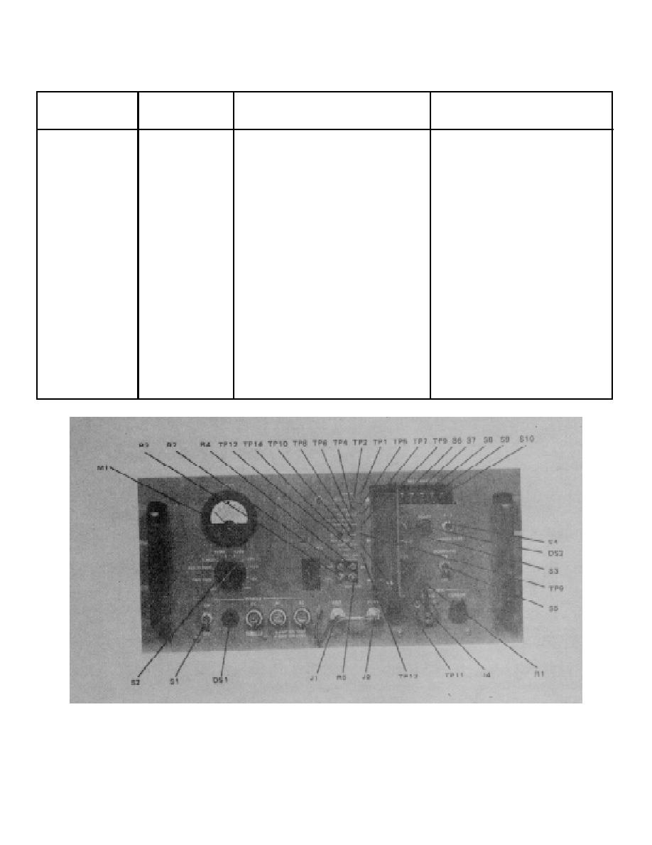
Figure 5-1. Radio Receiver-Transmitter RT-980/GRC-171, Test Point Location |
|
||
| ||||||||||
|
|  TO 31R2-2GRC171-2
TM 11-5820-815-14
NAVELEX 0967-LP-544-5010
Table 5-2. Test Points (Sheet 4 of 4)
REFERENCE
MODULE TO WHICH
DESIGNATION
TEST POINT
FUNCTION
TEST POINT APPLIES
A10A1DS1
POWER
Lamp is lit when power switch
Chassis A10
(lamp)
is closed and dc-dc converter
is operating.
A10A1DS2
READY
Lamp is lit when frequency
D/a servo amplifier A1, frequency
(lamp)
synthesizer (pll) is locked
synthesizer A2, and rf filter A7
and servo loop is balanced.
A10A1J4
MIC DYNAMIC
Handset audio input/output.
Audio A4
Provides vocal/aural input
or output as required.
A10A2J8
IF
Provides access to receiver
Receiver rf A3
(rear
output (10.7 MHz) or point of
panel)
injection of test signal.
A10A1J3
HEADSET
Provides vocal/aural output
Audio A4
as required.
A10A1J5
MIC CARBON
Provides vocal input
Audio A4
as required.
TP3-9894-017
Figure 5-1. Radio Receiver-Transmitter RT-980/GRC-171, Test Point Location
5-6
|
|
Privacy Statement - Press Release - Copyright Information. - Contact Us |
