 |
|||
|
|
|||
|
|
|||
| ||||||||||
|
|  TO 31R2-2GRC171-2
TM 11-5820-815-14
NAVELEX 0967-LP-544-5010
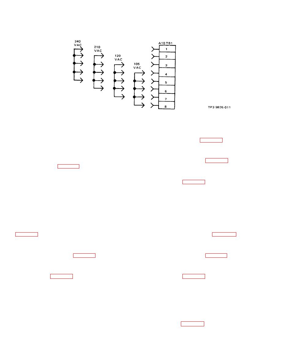
Figure 2-2. Primary Power Strapping
2-26.
PRIMARY POWER STRAPPING.
keying options are determined by strapping on the keyer
a. Extend RT-980/GRC-171 on the rack slides and
module and are shown in figure 2-4. To verify or change
remove the top cover.
the strapping, proceed as follows:
b. Check to ensure that the strapping on A10TB1
a. Remove keyer module A9. (Refer to removal/'
matches the station primary power supply. Change if
replacement procedures in chapter 5, section I, of this
necessary. Refer to figure 2-2.
manual.)
2-27.
AUDIO MODULE A4 STRAPPING.
b. Verify that strapping matches station require-
ments. Refer to figure 2-4. Change if necessary.
2-28. The audio module A4 has strapping options for
audio input level and transmitter keying. Audio input
c. Replace keyer module.
level strapping provides for normal level (-15 to +10 dB
mW) and -35 dB mW (-35 to -15 dB mW) audio inputs.
2-31.
NOISE BLANKER (P/O RECEIVER RF
The transmitter is normally keyed by applying a ground
MODULE A3).
or dc voltage to the center tap of the audio input line
transformer (A10A2J22-D/E) as determined by the
2-32. The noise blanker provides muting of the
strapping on audio module A4. The strapping options for
receiver from impulse noise received at the antenna.
audio input level and transmitter keying are listed in
The noise blanker has two strapping options. The
strapping options are listed in figure 2-5. To verify or
as follows:
change the strapping, proceed as follows:
a. Remove audio module A4. (Refer to removal/
a. Remove receiver rf module A3 (refer to removal/
replacement procedures in chapter 5, section I, of this
replacement procedures in chapter 5, section I, of this
manual.)
manual).
b. Verify that strapping matches station require-
b. Verify that strapping matches station require-
ments. Refer to figure 2-3. Change if necessary.
ments. Refer to figure 2-5. Change if necessary.
c. Replace audio module A4.
c. Replace receiver rf module A3.
2-29.
KEYER MODULE A9
2-33.
INITIAL CHECKOUT PROCEDURE.
2-30. The keyer module provides a tone/VOX keying
2-34. Upon completion of the installation and initial
option, current keying option, and four voltage keying
setup procedures, check to ensure that the equipment is
options. Tone/VOX keying option and the four voltage
operating properly by performing the operating
instructions in chapter 3, section II, of this manual.
2-7
|
|
Privacy Statement - Press Release - Copyright Information. - Contact Us |
