 |
|||
|
|
|||
|
Page Title:
R-1467(P)/GRC-144(V) and R-1467(P)/GRC-144(V) IF Gain and Carrier Alarm Test |
|
||
| ||||||||||
|
|  TM 11-5820-695-35
3-75.
R-1467(P)/GRC-144(V) and
c. Initial Teat Equipment Calibration..
R-1467(P)/GRC-144(V) IF Gain
(1) Turn on the AN/USM-161 and AN/URM-
and Carrier Alarm Test
52B and allow a 30-minute warmup period.
(2) Calibrate the AN/USM-161 using the
a. Test Equipment ad Materials.
procedures given in TM 11-6625-498-12.
(1) Signal Generator AN/URM-52B.
(3) Calibrate the AN/URM-52B at 4700 MIz
(2) Test Set, Radio Frequency Power AN/ USM-
using the procedures given in TM 11-6625-498-12.
161.
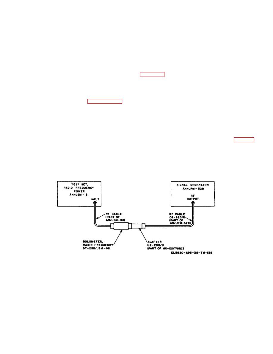
(4) Connect the test equipment as shown in
(3) Adapter UG-29B/U (part of Meter Calibration
Facilities Kit, MK-1207/GRC).
(5) On the AN/UM-I61, set the BIAS READ
b. Test Connections and Conditions. Performing
switch to READ, turn the POWER RANGE switch to 3.0
MW +5 DMB, and turn the POWER indicator dial for a
this test will affect the calibration of the T)54(P)/GRC-
dial scale indication of 1.0 on the center scale.
144(V) radio test set. Therefore, perform the radio test
set calibration procedure given in paragraph 3-61 upon
(6) Adjust the OUTPUT ATTEN control on the
completion of the test procedure given in d below.
AN/URM-52B for a null indication on the AN/USM-161
NULL INDICATOR meter.
(1) Set Switch, Waveguide SA-1679/GRC to
the TO LOAD (TEST) position.
(7) Adjust the POWER SET control on the
AN/URM-52B for an index indication of 0 dbm on the
(2) Disconnect the antenna waveguide from
OUTPUT ATTEN dial.
the rf entry panel on the external shelter wall.
(8) Turn off the AN/USM-161 and disconnect
(3) Disconnect the coaxial cable connected to
RF Cable CG-92D/U from Adapter UG-29B/U (fig. 3-32).
Coupler, Directional CU-1890/GRC.
(9) Set the OUTPUT ATTEN control on
(4) Record
the
R-1467(P)/GRC-144(V)
AN/URM-2B for a dial scale indication of -71 dbm.
operating frequency.
(5) The R-1467(P)/GRC-144(V)' must have a
minimum of two hours warmup period before performing
test procedure (d below).
Figure 3-32. Calibration of Signal Generator AN/URM-52B equipment connections.
Change 6
3-96
|
|
Privacy Statement - Press Release - Copyright Information. - Contact Us |
