 |
|||
|
|
|||
|
Page Title:
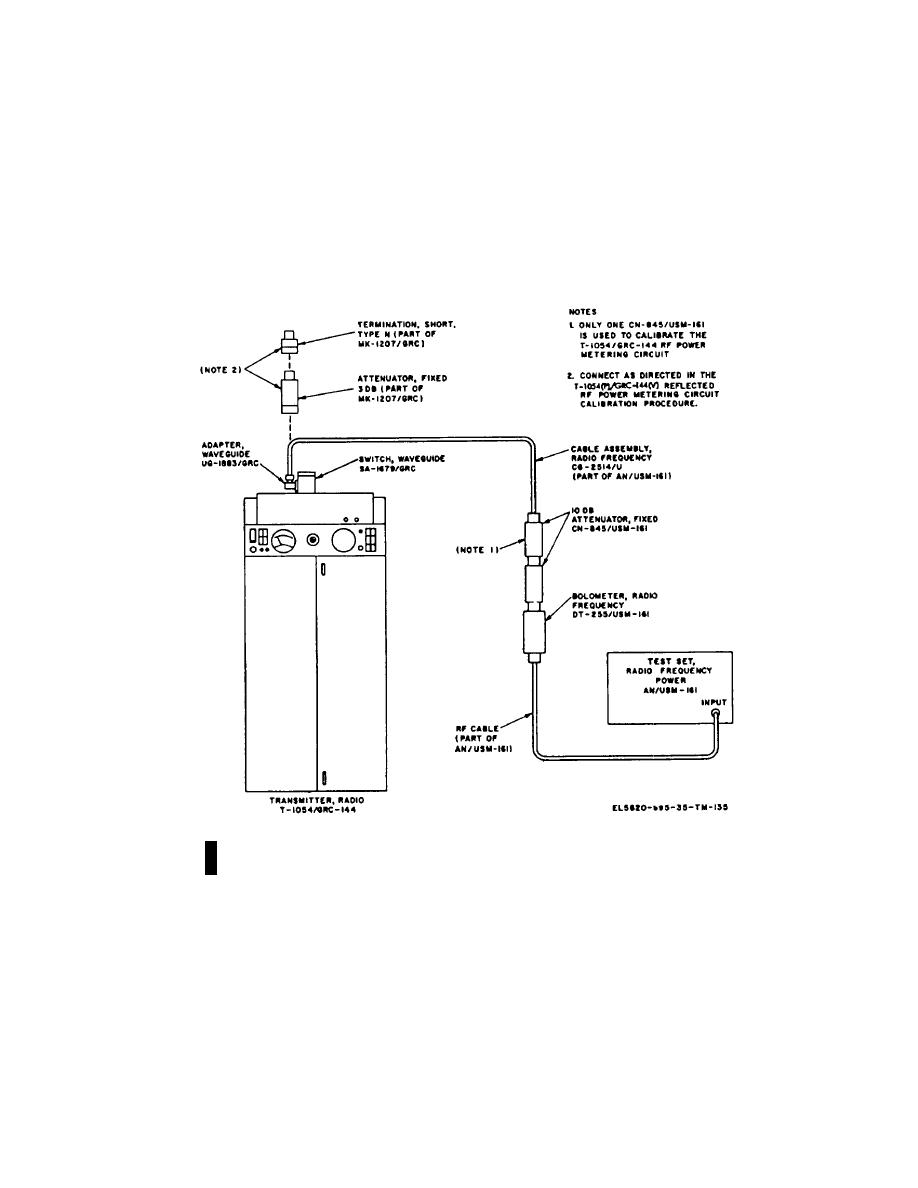
Figure 3-9. T-1054(P)/GRC-144(V) output power test setup. |
|
||
| ||||||||||
|
|  TM 11-5820-695-35
3-72.
T-1054(P)/GRC-144(V) and
T-1054 (P)A/GRC-144(V) Output
(2) Insure that Switch, Waveguide SA-1679/GRC-
Power Test
144 is set to the TO ANTENNA (NORMAL) position.
a. Test Equipment and Materials. Test Set, Radio
AN/USM-161 and allow a 80SO-minute warm- up period.
Frequency Power AN/USM-161.
Use the procedures given in TM11-6625-98-12 to
calibrate the AN/USM-161 after the warmup period is
b. Test Connections and Conditions.
over.
(1) Record the T-1054(P)/GRC-
144(V)operating frequency.
Figure 3-9. T-1054(P)/GRC-144(V) output power test setup.
Change 6
3-90
|
|
Privacy Statement - Press Release - Copyright Information. - Contact Us |
