 |
|||
|
|
|||
|
Page Title:
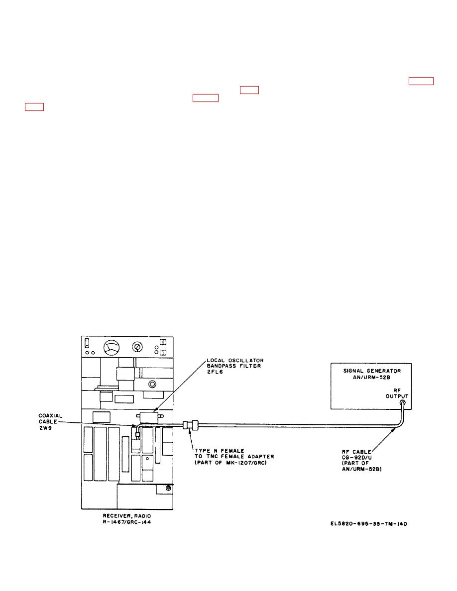
Figure 3-27. Calibration of R-1467/GRC-144 local oscillator metering circuits, equipment connections. |
|
||
| ||||||||||
|
|  TM 11-5820-695-35
b.
After the warmup period, calibrate the
l.
Record
the
R-1467/GRC-144
operating
AN/USM-161 using the procedures given in TM 11-
frequency.
6625-498-12 and calibrate the AN/URM-52B at 4700
m.
Connect the equipment as shown in figure
MHz using the procedures given in TM 11-6625-214-10.
c.
Connect the equipment as shown in figure
n.
On R-1467/GRC-144, set the preselector
bandpass filter 2FL4, post selector bandpass filter 2FL5,
d.
On the AN/USM-161, set the BIAS-READ
local oscillator 'bandpass filter 2FL6, and electrical
switch to READ, turn the POWER RANGE switch to
frequency synthesizer 2A14 controls to 4700 MHz.
3.0 MW +5 DBM, turn the COMP ATTENUATOR dial to
o.
Remove the dust cover from the ATTEN
0, and turn the POWER indicator dial for a dial scale
ADJ control on Coupler,, Directional CU-1890/ GRC
indication of 1.0 on the center scale.
and, using a screwdriver, turn the ATTEN ADJ control
e.
Adjust the OUTPUT ATTEN control on the
clockwise until mechanical stop is reached.
AN/URM-52B for a null indication on the AN/USM-161
p.
Turn the AGC SEL switch on 70 MHz
NULL INDICATOR meter.
intermediate frequency amplifier 2A5 to TEST.
f.
Adjust the POWER SET control on the AN/
q.
Turn meter selector switch 2A15A2S1' on
URM-52B for an index indication of 0 dbm on the
meter panel assembly 2A15A2 to CARRIER (IF).
OUTPUT ATTEN dial.
NOTE
g.
Turn the AN/USM-161 off and disconnect
If meter 2A15A2 indication is off
RF cable CG-92D/U from Adapter UG-29B/U (fig.
scale, when performing step r,
3432).
reduce the POWER SET control on
h.
Set the OUTPUT ATTEN control on AN/
AN/URM-52B for an on scale meter
URM-52B for a dial scale indication of -71 dbm.
reading. After performing step r,
i.
Set Switch, Waveguide SA-1679/GRC to
increase POWER SET control for a
the TO LOAD (TEST) position.
dial scale indication of -71 dbm on
the AN/URM-42B.
j. Disconnect the antenna waveguide from the rf
entry panel on the external shelter wall.
r.
Fine tune the SIGNAL FREQUENCY control
on AN/URM-52B for a peak indication on meter
k. Disconnect the coaxial cable connected to
2A15A2M1.
Coupler, Directional CU-1890/GRC.
Figure 3-27. Calibration of R-1467/GRC-144 local oscillator metering circuits, equipment connections.
3-82
|
|
Privacy Statement - Press Release - Copyright Information. - Contact Us |
