 |
|||
|
|
|||
|
Page Title:
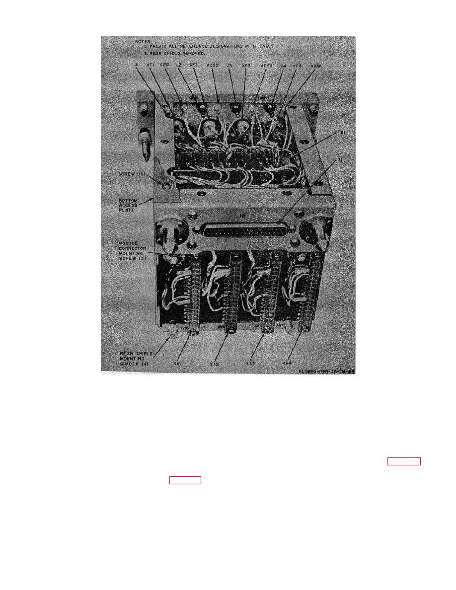
Figure 3-22. Power supply chassis assembly 2A1A5, parts location. |
|
||
| ||||||||||
|
|  TM 11-5820-695-35
Figure 3-22. Power supply chassis assembly 2A1A5, parts location.
(5) Slide power supply 2A1 out of electrical
(2) Tag and unsolder wires connected to
equipment cabinet 2A15.
component connector terminals of the connector to be
replaced.
(6) Loosen the two captive screws that secure
15/28v voltage regulator 2A1A1 to power supply chassis
(3) Remove the two screws, two nut and
assembly 2A1A5 and then remove 2A1A1 from the
washers securing component connector to power supply
chassis.
chassis assembly 2A1A5 and remove the connector.
(7) Repeat step (6) for regulators 2A1A2,
c. Replacement of Rack Mounted Component
2A1A4, and 2A1A3.
b. Removal of Rack Mounted Component
(1) Mount replacement connector in place of
removed connector using the two screws, two nuts and
washers removed in step b(3). Do not tighten the two
(1) Remove the four screws and associated
screws and nuts.
washers securing rear shield to power supply chassis
assembly 2A1A5.
3-64
|
|
Privacy Statement - Press Release - Copyright Information. - Contact Us |
