 |
|||
|
|
|||
|
Page Title:
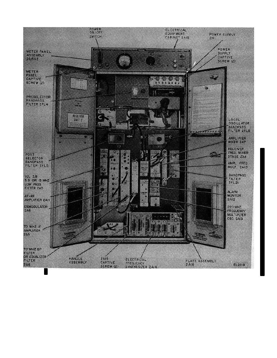
Figure 3-17. Receiver, Radio R-1467(P)/GRC-144(V) and R-1467(P)A/GRC-144(V) |
|
||
| ||||||||||
|
|  TM 11-5820-695-35
Figure 3-17. Receiver, Radio R-1467(P)/GRC-144(V) and R-1467(P)A/GRC-144(V)
align the meter mounting holes with those of the panel
(f) Remove and save the three lock
assembly.
nuts and screws that secure meter 2A15A2M1 to meter
panel assembly 2A15A2.
(b) Secure the meter in place with the
three locknuts and screws removed in (1)(f) above.
(g) Remove the meter from the meter
panel assembly.
(c) Position the meter panel assembly
2A15A2 upward and lock in position by use of the panel
(2) Replacement.
locking latch.
(a) Place new meter 2A15A2M1 in
position on front of meter panel assembly 2A15A2 and
Change 6
3-59
|
|
Privacy Statement - Press Release - Copyright Information. - Contact Us |
